background image

iNSTallaTiON 


installation

8

 | HSBB 200 S (GB) www.stiebel-eltron.com

11.3.2  Heating water connection

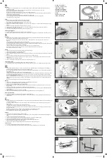
Installation example:

D

00000

70

88

7

1

2

1  Pipes carrying heating water

2  Pressure hose (available as accessory)

f

f

Thoroughly flush the pipes before connecting the heat pump. 

Foreign bodies (e.g. welding pearls, rust, sand, sealant, etc.) 

can impair the operational reliability of the heat pump. 

f

f

Install the heating water pipes (see chapter "Specification / 

Dimensions and connections").

Safety valve

1

3

2

D

00000

61

64

5

1  Drain hose (not part of the standard delivery)

2  Fasteners (not part of the standard delivery)

3  Drain (not part of the standard delivery)

f

f

Size the drain hose so that water can drain off unimpeded 

when the safety valve is fully opened.

f

f

Ensure that the safety valve drain hose is open to the outside.

f

f

Lay the safety valve drain hose with a constant fall to the 

drain.

f

f

Secure the drain hose to prevent any hose movement while 

water is discharged.

11.4  DHW connection and safety assembly

11.4.1  Safety instructions

!


Material losses

The maximum permissible pressure must not be exceed-

ed (see chapter "Specification / Data table").

!


Material losses

Operate the appliance only with pressure-tested taps.

Cold water line

Galvanised steel, stainless steel, copper and plastic are approved 

materials.

!


Material losses

A safety valve is required.

DHW line, DHW circulation line

Stainless steel, copper and plastic are approved materials. 

11.4.2  Installing the DHW circulation line, if applicable

A DHW circulation line with external DHW circulation pump can be 

fitted to the DHW circulation connection (see chapter "Specification 

/ Dimensions and connections").

f

f

Remove the sealing cap from the DHW circulation connection 

(see chapter "Specification / Dimensions and connections").

f

f

Connect the DHW circulation line.

11.4.3  DHW connection and safety assembly

f

f

Flush the pipes thoroughly.

f

f

Install the DHW outlet line and the cold water inlet line (see 

chapter "Specification / Dimensions and connections"). Con-

nect the hydraulic connections with flat gaskets.

f

f

Install a type-tested safety valve in the cold water inlet line. 

Please note that, depending on the supply pressure, you may 

also need a pressure reducing valve.

f

f

Size the drain pipe so that water can drain off unimpeded 

when the safety valve is fully opened.

f

f

The safety valve drainage aperture must remain open to 

atmosphere.

f

f

Install the safety valve drain pipe with a constant fall to the 

drain.

11.5  Filling the system

Heating circuit water quality

Carry out a fill water analysis before the system is filled. This 

analysis may, for example, be requested from the relevant water 

supply utility.
To avoid damage as a result of scaling, it may be necessary to 

soften or desalinate the fill water. The fill water limits specified 

in chapter "Specification / Data table" must always be observed.

f

f

Recheck these limits 8-12 weeks after commissioning and 

during the annual system service.

Summary of Contents for 236916

Page 1: ...OPERATION AND INSTALLATION Cylinder and hydraulic module HSBB 200 S GB...

Page 2: ...ring diagram 20 16 4 Details on energy consumption 22 16 5 Data table 22 GUARANTEE ENVIRONMENT AND RECYCLING SPECIAL INFORMATION The appliance may be used by children aged 8 and older and persons with...

Page 3: ...nt the risk are listed 1 2 2 Symbols type of risk Symbol Type of risk Injury Electrocution Burns burns scalding 1 2 3 Keywords KEYWORD Meaning DANGER Failure to observe this information will result in...

Page 4: ...nce description The appliance comprises a hydraulic module and an integral DHW cylinder and is equipped with a removable front casing The appli ance is connected hydraulically and electrically to the...

Page 5: ...If you cannot remedy the fault notify your qualified contractor To facilitate and speed up your request provide the number from the type plate 000000 0000 000000 No 000000 0000 000000 Made in Germany...

Page 6: ...osses Store and transport the appliance at temperatures be tween 20 C to 60 C Handling If possible transport the appliance to the installation site on the non returnable pallet Alternatively transport...

Page 7: ...ements or steel pipes Material losses The products of corrosion e g rusty sludge can settle in the heating system components and can result in a lower output or fault shutdowns due to reduced cross se...

Page 8: ...ine Stainless steel copper and plastic are approved materials 11 4 2 Installing the DHW circulation line if applicable A DHW circulation line with external DHW circulation pump can be fitted to the DH...

Page 9: ...re position so that the heating circuit and the heat exchanger for DHW heating are filled evenly When power is switched on the 3 way diverter valve automatically switches to heating mode To fill or dr...

Page 10: ...dance with relevant regulations Before any work on the appliance disconnect all poles from the power supply WARNING Electrocution Only use a permanent connection to the power supply Ensure the applian...

Page 11: ...rol voltage Appliance function Effect of the electric emergency booster heater Mono energetic operation If the heat pump undershoots the dual mode point the electric emergency booster heater safeguard...

Page 12: ...xtra low voltage X1 1 CAN A L H L H CAN connection for heat pump and WPE heat pump extension X1 2 CAN B L H L H CAN connection for FET remote control and ISG Internet Service Gateway X1 3 Signal Earth...

Page 13: ...PE 2nd heat source heating X2 13 L N PE L N PE Cooling X2 14 Mixer OPEN N PE Mixer CLOSE 5 N PE 6 Mixer heating circuit 2 X2 14 1 Mixer OPEN X2 14 2 Mixer CLOSE X2 15 Mixer OPEN N PE Mixer CLOSE 5 N P...

Page 14: ...doors or air ducts Observe the following minimum clearances 2 5 m above the ground and 1 m to the side of windows and doors Installation f f Remove the cover f f Secure the base with the screw suppli...

Page 15: ...e observe the rules of the relevant Health Safety at Work Act during commissioning For further details check with your local authorising body 13 1 Checks before commissioning the heat pump manager Mat...

Page 16: ...Condensation caused by the temperature falling below the dew point can lead to material losses HSBB is there fore exclusively approved for area cooling Adjusting the heat pump manager settings for ar...

Page 17: ...fication Dimensions and connections Checking replacing the protective anode f f Check the protective anode after the first two years of use and replace if necessary Check that the maximum transition r...

Page 18: ...80 92 92 177 347 432 517 10 20 177 D0000070858 HSBB 200 S GB b01 Entry electrical cables c01 Cold water inlet Male thread G 1 c06 DHW outlet Diameter mm 22 c10 DHW circulation Male thread G 1 2 c12 Sa...

Page 19: ...m tundish with continuous fall 11 Equipotential bond 12 Drain valve 13 Cylinder 14 DHW outlet 15 T P valve 16 Metal discharge pipe D1 from T P valve to tundish 17 Expansion vessel 18 Expansion relief...

Page 20: ...heating circuit BT01 Temperature sensor heat pump flow BT02 Temperature sensor heat pump return BT06 Temperature sensor heat pump buffer cylinder not for HSBB or TSBB eco BT20 Temperature sensor DHW...

Page 21: ...X1 7 Connector heating circuit temperature sensor 3 AA01 X1 8 Connector DHW cylinder sensor BT20 AA01 X1 9 Connector source sensor AA01 X1 10 Connector heat source 2 AA01 X1 11 Connector flow cooling...

Page 22: ...l min 22 6 Max operating temperature heating water C 89 Application limits Max permissible pressure Design Pressure DHW cylinder MPa 0 7 Test pressure DHW cylinder MPa 1 5 Max permissible pressure Des...

Page 23: ...cordance with national regulations HSBB 200 S GB set Values Expansion vessel volume l 12 Expansion vessel pre charge pressure MPa 0 15 Nominal design flow rate of heating system at A 7 W35 and 7 K m h...

Page 24: ...land STIEBEL ELTRON OY Kapinakuja 1 04600 M nts l Tel 020 720 9988 info stiebel eltron fi www stiebel eltron fi France STIEBEL ELTRON SAS 7 9 rue des Selliers B P 85107 57073 Metz C dex 3 Tel 0387 743...

Reviews: