STIEBEL ELTRON 236916, Operation And Installation
The STIEBEL ELTRON 236916 is a high-quality water heater that provides efficient water heating for your home. For detailed instructions on operation and installation, you can download the free manual from manualshive.com. This manual will guide you through the setup process to ensure optimal performance of your water heater.
Share
Download


Reviews:
No comments
Related manuals for 236916
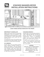
LSE7806ACE
Brand: Maytag Pages: 14

SPORTEC base FR
Brand: KRAIBURG Pages: 2

AD 9608
Brand: Adler Europe Pages: 68

BeNext
Brand: iHome Pages: 13

REFRESH-BUTLER
Brand: V-ZUG Pages: 68

DRY:SOON 24576
Brand: Lakeland Pages: 24

SC837-00
Brand: Safe Pages: 72

Everyday Rotary 37
Brand: Hills Pages: 12

K1-4341
Brand: Lefroy Brooks Pages: 10

PC13DDS
Brand: SoftStep Pages: 4

TOUCHLESS TRASH CAN MT02SS
Brand: Itouchless Pages: 2

SN2268
Brand: GoodOne Pages: 18

GGL INTEGRA
Brand: Velux Pages: 50


