

Installation procedure
Proximity Reader LXS & AVX – R11 Variant (ISO2 / Wiegand)
© STId 2008 – NI006A02 - Ed. 26/08/2008
1
••••
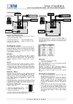
Wiring diagram
2
••••
Recommended cables
Use a multi-conductor cable, pair shielded. When power is
supplied with the same cable we recommend:
1 pair AWG24 for up to 30 m
1 pair AWG35 for up to 50 m
2 pairs AWG24 for up to 60 m
2 pairs AWG35 for up to 100 m
3 pairs AWG24 for up to 100 m
3
••••
Pull-ups resistors
If pull-up resistors for data signals are not present on the host
unit to which the reader is connected, it is necessary to add
10K
Ω
resistors on the reader connector. They are to be
connected as shown on the diagram above.
4
••••
Buzzer
The buzzer gives an indication of correct read, not depending
on the eventual authorizations or access rights given to a card.
It will emit a brief sound as soon as a card or tag is read. It is
possible to shut it off by removing the jumper located just
nearby the buzzer.
5
••••
Led
The led is bicolor (red & green). When the reader is powered
on, it is amber (red & green). It can be driven by the remote
system to light it either red or green, by bringing a 0V
respectively on the red or green inputs of the reader’s
connector.
6
••••
« Mode » input
By default, when this input is not connected, the reader will
automatically delay the transmission of the code every 2
seconds when a card is left in the reading field. If a new card is
shown to the reader before this time laps, its code will be
transmitted immediately.
When connected, this input cancels the delay in the
transmission rate of a same card left in the reading field. In
other word, the reader will transmit the code as fast as it can.
To cancel the delay, connect the “Mode” input with 0V as
shown below:
1. Power off the reader.
2. Connect the input Mode to 0V.
3. Power on the reader.
⇒
Check if the reader is operating properly by presenting a
card. The reader should then beep quickly on each reading.
4. To come back to the initial configuration, power off the
reader, then unplug the wire between “Mode” and “0V”. Power
the reader on. Now, when a card is left in the reading area, the
reader will beep only every two seconds.
7
••••
Installation
•
Connect the reader
•
Test the reading and communication.
•
Attach the reader on the wall, or on standard electrical
flush-boxes. Install the screw caps.
Caution: Screw caps are made to be hard to remove
once installed. We recommend to make all the tests
before installing them.
8
••••
Precautions for installation
•
Power supply tension at the reader’s connector should be
strictly comprised between 10.5V and 15V.
•
Keep the reader away from computer or power cables as
much as possible. They can generate an electrical
perturbation that is function of their proximity and
radiation level.
•
Distance to respect between two readers : parallel plan :
30 cm – Same plan : 40 cm – Perpendicular : 25 cm.
•
If the reader is mounted on a metallic surface it can affect
the reading distance. To get the maximum reading
distance, the reader should be installed at no less than 7
cm from any metallic surface.
ISO 2
Wiegand
0
0V
0V
1
+12 VDC
+12 VDC
2
Code
Data 0
3
Data
Data 1
4
Clock
Clock
5
Mode
Mode
6
Green Led
Green Led
7
Red Led
Red Led
0V
+12V
Code / Data 0
Data / Data 1
Clock
Mode
Pull-ups resistors
connection details
0
1
2
3
4
5
6
7
10 k
10 k
10 k
+
1
2
V
2
3
4
Power
12V / 0,5A min.
Data signals
LEDS commands
JUMPER
Open : Buzzer off
Closed : Buzzer on
Pull-ups resistors
connection details
0
1
2
3
4
5
6
7
10 k
10 k
10 k
+
1
2
V
2
3
4
Power
12V / 0,5A min.
Data signals
LEDS comm ands
JUMPER
Open : Buzzer off
Closed : Buzzer on
Pull-ups resistors
connection details
0
1
2
3
4
5
6
7
10 k
10 k
10 k
+
1
2
V
2
3
4
10 k
10 k
10 k
+
1
2
V
2
3
4
Power
12V / 0,5A min.
Data signals
LEDS comm ands
JUMPER
Open : Buzzer off
Closed : Buzzer on


