


Hardware layout and configuration
UM1817
22/58
DocID026902 Rev 3
Note:
The temperature result measured from STLM75M2F would be a little higher than the
ambient temperature due to the power dissipation of the components on the board.
2.14 Smartcard
STMicroelectronics smartcard interface chip ST8024L is used on the STM32091C-EVAL
evaluation board for asynchronous 1.8 V, 3 V and 5 V smartcards. It performs all supply
protection and control functions based on the connections with the STM32F091VCT6 listed
in
Smartcard operates correctly when VDD > 2.7 V.
2.15 CAN
STM32091C-EVAL evaluation board supports one channel of CAN2.0A/B compliant CAN
bus communication based on 3.3 V CAN transceiver. The high-speed mode, standby mode
and slope-control mode are available and selectable by setting JP3 (see
).
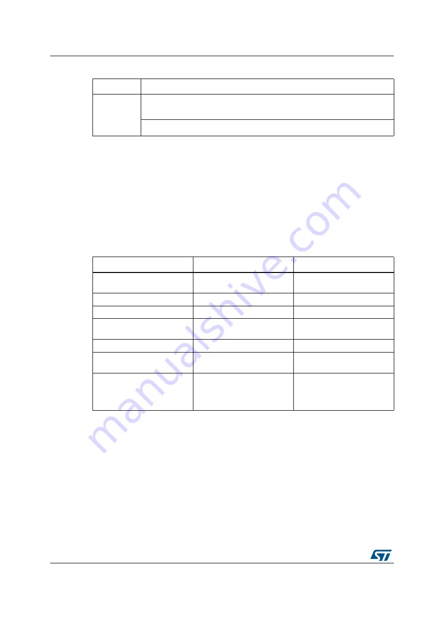
Table 13. Temperature sensor or related solder bridge
Solder Bridge
Description
SB1
I
2
C address A0 is 0 when SB1 is open
(Default setting)
I
2
C address A0 is 1 when SB1 is closed.
Table 14. Connection between ST8024L and STM32F091VCT6
Signals of ST8024L
Description
Connect to STM32F091VCT6
5 V/3 V
smartcard power supply
selection pin
PC2
I/OUC
STM32 data I/O line
PA2
XTAL1
Crystal or external clock input
PD7
OFF
Detect presence of a card
,
Interrupt to MCU
PC3
RSTIN
Card Reset Input from MCU
PA3
CMDVCC
Start activation sequence input
(active low)
PA7
1.8V
1.8 V V
CC
operation selection.
Logic high selects 1.8 V
operation and overrides any
setting on the 5 V/3 V pin.
PC1


