58
fullload
speedrange
100%
90%
80%
70%
60%
50%
40%
30%
B
C
D
RPM
A
OUTPUT
POWER
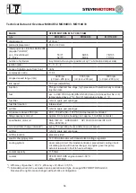
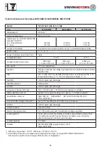
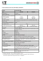
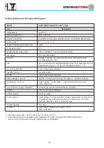
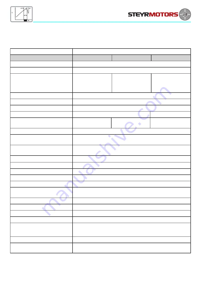
Technical Data and Overview MO144M38, MO164M40, MO174V40
MAKE
STEYR MOTORS M 14 TCAM
type
MO144M38
MO164M40
MO174V40
displacement
2133 cm³
piston displacement
85,0 x 94,0 mm
rated power acc. EN ISO 8665:2006
(impeller*) KW/HP
Jet – Drive/Inboard
Z – Drive
103/138
101/136
116/156
114/154
121/165
119/162
number of cylinders
4-cylinder in-line engine (position of cyl. 1 at vibration damper side)
ignition order
1 – 3 – 4 – 2
sense of rotation, seen from front
right
compression ratio
17.5:1
17.0:1
propped speed range (rpm)
3800 rpm
(+0 rpm/–300 rpm)
4000 rpm
(+0 rpm/–300 rpm)
4000 rpm
(+0 rpm/–300 rpm)
idle speed
700 rpm (adjustable)
injection
Plunger activated, two stage, high pressure with electronically controlled
injection rate
fuel
acc. to CEC RF-03-A-84 (DIN EN 590) Cetan >49; diesel fuel No. 2-D,
temperature above –7 °C; No.1-D, temperature below –7 °C
fuel filter
refer to spare part catalogue
fuel filter location
intake-sided
air filter
refer to spare part catalogue
oil pressure above 2000 rpm
400 – 700 kPa (58 – 101 PSI) microprocessor controlled
filling capacity motor oil
approx. 8,0 l engine housing (incl. approx. 1 l oil filter contents)
specification motor oil
SAE 10W-40 ACEA E6/E7 API CI-4/CH-4/CG-4/CF-4,CF
P/No. Z050316-4
oil and oil filter change intervals**)
every 150 operating hours and/or once per season
oil filter
refer to spare part catalogue
oil filter location
pressure-sided
electric charging system
14 V/90 A alternator with transistorized voltage regulator
cooling system
dual cooling circuit; thermostat-controlled, pressurized cooling circuit;
circulating pump with heat exchanger on engine; governor pump,
external raw water circuit to heat exchange
coolant capacity
11,5 liters
coolant
STEYR MOTORS engine coolant –36 °C
P/No. Z011785/0
*) Efficiency of gearbox = 97,0 %, efficiency of Z-Drive = 95,5 %
**) Extended periods to be evaluated upon application and type of usage STEYR MOTORS GmbH.
Reserves the right to make changes without notice or obligations.
Summary of Contents for MO114K33
Page 2: ...This Page is intentionaly blank ...
Page 5: ...5 This page is intentionaly blank ...
Page 6: ...6 SAFETY PRECAUTIONS Safety Precautions 7 Introduction 7 ...
Page 21: ...21 This page is intentionaly blank ...
Page 49: ...49 This Page is intentionaly blank ...
Page 91: ...91 Wiring diagram MO 12 V 4 cyl from engine s n 482330250 ...
Page 92: ...92 Wiring diagram MO 24 V 4 cyl from engine s n 482330250 ...
Page 93: ...93 Wiring diagram MO 12 V 2 pol 4 cyl from engine s n 482330250 ...
Page 94: ...94 Wiring diagram MO 24 V 2 pol 4 cyl from engine s n 482330250 ...
Page 95: ...95 Wiring diagram MO E Box external 4 cyl from engine s n 482330250 ...
Page 96: ...96 Wiring diagram MO E Box external 2 pol 4 cyl from engine s n 482330250 ...
Page 101: ...101 Wiring diagram SE E Box 12V 6 cyl ...
Page 102: ...102 SE Series Wiring diagram SE E Box 24V 6 cyl ...
Page 103: ...103 SE Series Wiring diagram external SE E Box 6 cyl ...
Page 104: ...104 Wiring diagram SE E Box 12 V 4 cyl ...
Page 105: ...105 Wiring diagram external SE E Box 12 V 4 cyl ...
Page 106: ...106 Wiring diagram Instument CAN Panel 12 24V ...
Page 107: ...107 Wiring diagram Instument CAN Panel Solas 12 24V ...

