1
© 2005 Stevens AeroModel all rights reserved.
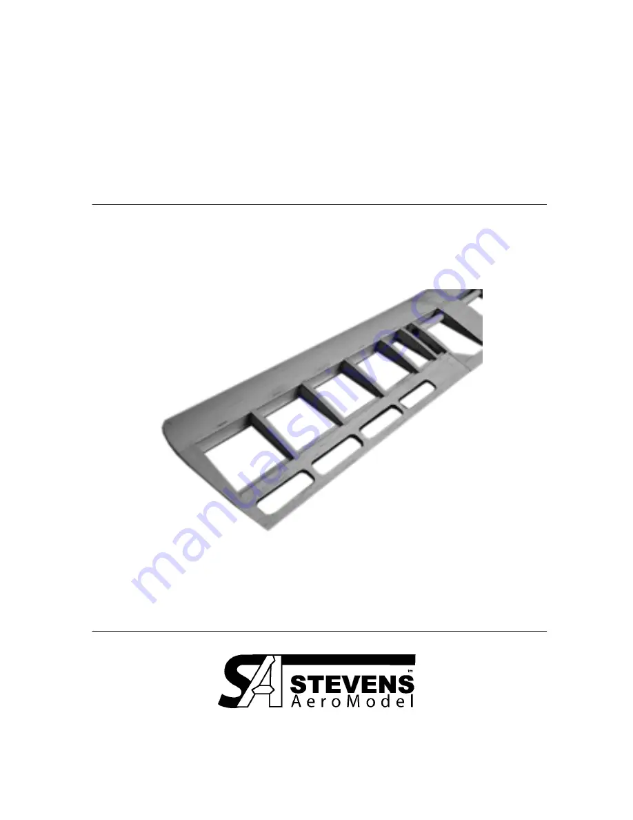
SQuiRT
Aileron Wing Kit
V1.02b
Span 38” / Area 260Sq.”
Page 1: ...1 2005 Stevens AeroModel all rights reserved SQuiRT Aileron Wing Kit V1 02b Span 38 Area 260Sq...
Page 2: ...es the right to change or modify this warranty without notice In that Stevens AeroModel has no control over the final assembly or material used for final assembly no liability shall be assumed nor acc...
Page 3: ...l Horns 1 Du bro 845 E Z Connectors 2 Pkg Recommended Finishing Items 1 One roll of AeroFILM covering available from www stevensaero com Suggested Electronics 1 4 Channel Transmitter 2 2 Hitec HS 55 S...
Page 4: ......
Page 5: ...truction and blends stick and tissue design methods of the past with state of the art CAD technology and precision interlocking laser cut parts the result is something you will find truly exceptional...
Page 6: ...m CA spills Cut tube down one side and unfold over your plans CA glue will not stick to this poly tube We suggest that as you assemble this wing you only tack glue the parts at the tab notch locations...
Page 7: ...y in the 1 16 ply spar doubler S2 between ribs R2 and on the aft side of spar S1 retain the ply doubler by slipping ribs R1 over the spar and doubler Wick thin CA in between the balsa S1 spar ply doub...
Page 8: ...as indicated on the plan sheet etched arrows up Next join parts TE1 to either side of TE2 the arrows etched on the surface of TE1 should face those of TE2 Finalize center section trailing edge by ins...
Page 9: ...should face the front or leading edge of the wing You ll see where this orientation is important as the tip of each trailing edge part is tapered up at an angle to match the wing tips Using a new sha...
Page 10: ...tween ribs R2 and R2a SR1 is notched to only fit in one direction Once satisfied with the fit glue both parts SR1 and the paper servo guide tube installed in the previous step Install lower cap strips...
Page 11: ...tion of R2a as indicated on the plan sheet Finally on the opposite side of R2 install triangular part TE1a Sheet center wing section starting with W6 Double check that W6 is centered between R1 prior...
Page 12: ...the root securing the W2 D Loc sheeting with CA glue at each interlock point Complete assembly by slightly pinching D Tube together at the leading edge of each rib then wicking in Thin CA along the in...
Page 13: ...ainder of the leading edge cut sand off excess dowel that extends beyond wing tip Sand the wing tips round Sand the trailing edge cap strips and the center section wing sheeting to taper into the trai...
Page 14: ...htening hole pieces Punch out the lightening holes lightly sand the top bottom and inside edge of aileron Notice that you have a Right and Left aileron also notice that the ailerons will hinge from th...
Page 15: ...nd double with another length of tape along the underside of the aileron wing hinge point Slot the covering in the ailerons over the laser cut control horn pocket Install the fiberglass control horns...
Page 16: ...eeds A model that always drops one wing at stall will often have a bit of twist in the wing or wash in on the wing that drops Set control surface throws Suggested Control Surface Travel Elevator 1 2 R...
Page 17: ...was hired by United Airlines as a Boeing 737 First Officer Since that time he has flown as a First Officer on the Boeing 737 200 737 300 Airbus A320 Boeing 767 757 and as a Captain on the Boeing 737 3...
Page 18: ...ane point of view ailerons present several changes to your maneuvering With ailerons we ve split roll control from yaw control The ailerons control the roll of the airplane while the rudder controls t...
Page 19: ...t require rudder coordination I do find however that the vast majority of aileron trainers require rudder inputs for coordinated flight That said your model will turn with just aileron inputs it just...
Page 20: ...crosswind takeoffs and landings The second common use of slips is to increase the rate of descent by increasing the drag on the airplane With an aileron equipped model it is possible to yaw the aircr...
Page 21: ...ing let it yaw into the wind and establish a crab discussed in the crosswind landing section to maintain the runway centerline during the climb out Crosswind Landings Crosswind landing you say I thoug...
Page 22: ...ipping approaches either for crosswind purposes or altitude loss is that there is significantly more drag on the model so you will notice a higher than normal rate of descent You may need to fly the a...
Page 23: ...the on line cart the discount will be applied regardless of payment option This offer is only available at www stevensaero com About the Book Written by an accomplished full scale pilot and R C pilot...