background image

BJ5-620 Appendix 72 

of 

73 


716 

Fixing bolt for cylinder bolt  
DIN912 – M16x45 – 12.9 

717 4 

Grease 

nipple 

GB1152-89-M8x1 


800  

Hydraulic 

801 

Cylinder for pusher ø125 × ø63 × 1000 

802 

Hydraulic unit SHC-406 A 

803  

Piping 


804  

Connectors 

805 

Set of sealing for pusher cylinder 

806 

Oil filter SP-10 


900  

Electrical parts 

901 

Safety switch CAZ15zvrk 

902 

Small control box 

903 1 

Control 

panel 

904 

Proximity switch II0297 

905 

Cable for Proximity switch E10200 


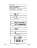
Hydraulic Unit Spare Parts List 

Pos Description 

Standard 

Pc Supplier 

1 Suction 

filter 

MF-06 

CLC 

2 Suction 

filter 

MF-08 

CLC 

Electric motor 

20HPX4P(straight system)380V 

Qunce 

4 Gear 

pump 

PVL12-12-33 

Xinhong 

5 Oil 

cooler 

JC-YL-AH1012 


6 Check 

valve 

CRG-03-1-10 

CLC 

7 Check 

valve 

CRG-03-1-10 

7Ocean 

Solenoid control relief valve 

DBW10-22AL-2-DC-DN+MSL-02P 1 

7Ocean 

Solenoid control relief valve 

BSG-03-1PN-2-DC24-DN10+ MSL-02P 

7Ocean 

10 
11 

Pressure valve 
Solenoid valve 

2-1/2“ – 25Mpa 
DG07-E1-521C-T-DC24-DN-71 

1 7Ocean 

12 

Throttle and check valve 

PT-03 

FTB 

13 

Throttle and check valve 

MTC-04-B-O-10 

7Ocean 

14 Pressure 

switch 

PS-02-3-10 

1 7Ocean 

15 Fluid 

level 

LS-3“ 

1 CLC 

16 Filler 

breather 

AB-1163 

1 CLC 

17 

Return suction filter 

SP-10 

7Ocean  

18 Tank 

160l 

1 7Ocean 

19 Solenoid 

valve 

DSD-G02-6C-DC24-31 

1 7Ocean 

20 
 

Modular pilot check valve 

MPC-02-W1-10 

7Ocean 


Summary of Contents for SXS 1500

Page 1: ...__________________ _________________________ _________________________ _________________________ _________________________ _________________________ We are committed to a continuing program of product...

Page 2: ...nvoice is available upon request The original Bill of Lading is attached to our original invoice If the shipment was prepaid write us for a receipted transportation bill Advise customer service regard...

Page 3: ...More detailed information is given at the relevant administrative authority i e regional and national Water Conservation Bureau and Environmental Protection Agencies Only deposit the material to be d...

Page 4: ...ION 22 3 1 Uncrating the Equipment 22 3 2 Electrical Connections 23 3 3 Initial Start up 25 CHAPTER 4 OPERATION 27 4 1 Start up 27 4 2 Operation Procedures 27 4 3 Shut down 29 CHAPTER 5 MAINTENANCE 32...

Page 5: ...o information for operating the equipment safely and efficiently The Maintenance chapter is intended to serve as a source of detailed assembly and disassembly instructions for those areas of the equip...

Page 6: ...re properly aligned and that tension is at its maximum Extreme care should be taken to see that all bolts are properly tightened at all times During the operation of the machine rotor knife bolts may...

Page 7: ...l objects should be left on or around the machine Any tools or other metal objects that mistakenly fall into the hopper feed opening can cause severe damage to internal cutting chamber rotor and scree...

Page 8: ...t is imperative to be aware of these risks in order to avoid accidents To avoid danger please observe all safety advice provided Type of Danger Activity Possible Consequences Preventative Measures Dan...

Page 9: ...g the terminal box switch too off O Failure of Emergency Stop function All activities Serious injury or death It must be guaranteed that failure of an Emergency Stop button is displayed and leads to a...

Page 10: ...to the manual s specifications For further information on granulator safety installation and operation see the American National Standard for Plastics Machinery Granulators Pelletizers and Dicers Used...

Page 11: ...etal parts being fed into the machine The material in the hopper is shredded by the cutters on the rotor This shredding process is repeated as often as required until the whole diameter of the screen...

Page 12: ...he grinding material can be fed into the shredder in the following ways Manual in feed of the material directly into the in feed hopper Manual in feed of the material with the help of an additional in...

Page 13: ...fly back during size reduction is available Additional In feed Device If the machine has an optional in feed device such as a conveyor belt please refer to the additional information about the accesso...

Page 14: ...s and Bed Knives Rotor cutters bed knives The material is shredded between the cutters assembled on the rotor and the bed knives that are mounted in a fixed position in the machine lower section All r...

Page 15: ...een The rotor is arranged on roller bearings that are situated outside the housing The V belt pulley is attached to the rotor axis with a taper brush The rotor is dynamically counter balanced and has...

Page 16: ...g by screws in standard execution The screen is slightly larger in radius than the cutting circle of the rotor cutters The screen perforation is selected according to the desired grain size of the shr...

Page 17: ...73 Discharge of Shredded Material Normally the shredded material will be discharged onto a conveyor belt Options include a discharge with blower or with a screw conveyor 1 Hydraulic cylinder 2 Screen...

Page 18: ...inders move the ram back and forth The ram moves automatically after switching on the hydraulic system and the shredder when the machine is operated in automatic mode NOTE The ram can be moved by hand...

Page 19: ...ve devices The use of faulty or manipulated protective devices is strongly prohibited Safety Device for Machine and Hopper Doors The shredder can only be operated if the doors are closed deactivating...

Page 20: ...machine according to the current legal safety regulations if the machine is delivered without drive motors upon customer request Safety Markings Safety markings are attached to the machine Should one...

Page 21: ...Emergency Stop buttons in case of an emergency CAUTION The Emergency Stop must be activated in all situations where injury or damage could result Re operation 1 Eliminate cause of Emergency Stop 2 Unl...

Page 22: ...tors or the sun Room temperature 41 to 104 F 5 to 40 C Relative atmospheric humidity according to DIN 40040 15 to 70 indoor NOTE By humidity levels higher than 70 apply anticorrosive agent to the meta...

Page 23: ...t use blocks to place underneath the machine use metal strips to prevent buckling of the base frame Make sure that an even distribution of weight is achieved on all the points of support 3 2 Electrica...

Page 24: ...The machine may only be operated with installed Emergency Stop buttons An Emergency Stop button must be installed at the control cabinet and at the grinding material in feed if no Emergency Stop butt...

Page 25: ...h the freight company and report it to the manufacturer After setting up for service and before starting up for the first time you must carry out necessary checks according to the section Machine Chec...

Page 26: ...and check rotational direction 9 Allow machine to run for approximately 10 minutes without shredding material 9 Connect material discharge device and in feed device check rotational direction drives 9...

Page 27: ...tter 9 The machine and hopper doors are closed 9 All safety devices including those of the installed material in feed and discharge devices are checked and operative Switch ON Machine 1 Switch ON the...

Page 28: ...Emptying the Screen 1 Switch off the shredder at the main switch 2 Safeguard main switch using a padlock 3 Open the machine door 4 Safeguard machine door 5 Pivot the screen support downwards by pushi...

Page 29: ...er the running direction is correct facing the motor blade the motor should run clockwise if the direction is not correct change the position of 2 of the 3 electrical wires 5 Run motor operate the mag...

Page 30: ...BJ5 620 Operation 30 of 73 Figure Hydraulic Set up SQ1 SQ2 SQ3 SQ4 9M Pa 9M Pa 15M Pa 125 63 33m l r ec 12m l r ec...

Page 31: ...Shut down Switch OFF Machine 1 Switch OFF the material in feed device accessories 2 Wait until the remaining material has been shredded and then switch OFF the shredder main switch to 0 3 Switch OFF...

Page 32: ...he following after every 8 operation hours Check protective devices Check cutting knife mountings Check condition of cutting knives Perform the following after every 40 operation hours Check V belt te...

Page 33: ...modifying them Cleaning the Machine WARNING Danger of cutting caused by sharp cutting knives even when the rotor is not operating Serious injury especially to the hands and fingers can result Wear pr...

Page 34: ...nufacturer or ask the service department for help Replacing the Rotor The rotor s design is heavy duty design so a replacement is necessary only after a crash i e a hammer fall inside Dismounting and...

Page 35: ...e designed so a bearing replacement is necessary only in exceptional cases Dismounting and mounting of the bearings requires specialist knowledge and a careful working method In addition to the follow...

Page 36: ...Put back the rotor cover plates 9 Put in the screen 10 Pull on V belts and adjust the V belt tension force 11 Attach the V belt cover 12 Carry out a test run NOTE The roller bodies will be damaged unl...

Page 37: ...eplacing or Refilling Lubricant Fill the bearings uniformly with grease until all operating surfaces are well greased For the rotor bearings a lubricant quantity of one third to a maximum of half of t...

Page 38: ...overheating Mounting and dismounting of the bearings must be carried out in accordance with the instructions in this operation manual see replacing the bearings 1 Open the bearing 2 Remove the bearin...

Page 39: ...P BP ENERGREASE LS 3 CASTROL CASTROL SPHEEROL AP 3 ESSO Beacon 3 FUCHS FUCHS Grease 1200 FUCHS Grease FWA 220 SHELL SHELL Alvania Grease 3 MOBIL OIL MOBILUX 3 WISURA WISURA Liba L 3 Zeller Gmelin ZET...

Page 40: ...f 73 Mounting and Dismounting TAPER LOCK Tensioning Element The motor and the gear V belt pulleys are attached to the shaft using a TAPER LOCK tensioning element The disks must be dismounted for certa...

Page 41: ...en must be checked regularly in order to keep the throughput of the shredder and the quality of the shredded material constant The screen may be damaged dirty or not suitable for the shredding materia...

Page 42: ...ler centres 3 Determine the belt sag force F for each belt at 16 mm sag if sag b is equal to 1 m distance between roller centres Do this by measuring the distance between roller centres at a right ang...

Page 43: ...e V belt 5 Mount the V belt cover Checking V belt condition replacing V belt CAUTION Danger of pulling into machine caused by running V belts Hair jewelry etc can be pulled into machine without proper...

Page 44: ...en loosened and tightened again several times New screws of the same material quality must replace the cutting knife mounting screws after they have been loosened and tightened several times Checking...

Page 45: ...ew 2 7 Loosen the bolt using a high quality Allen key 10 mm Knock the Allen key lightly with a hammer to loosen it if necessary 8 Take out the cutter mounting screw the washer and the cutter Dismounti...

Page 46: ...ecessary 11 Take out the cutter holder mounting screws 4 12 Remove the cutter holder with the delivered Extractor NOTE See drawing in Dismounting the rotor knives WARNING Danger of cutting caused by s...

Page 47: ...ghtly knock key if necessary 10 Take out the knife mounting bolt and knife WARNING Danger of cutting caused by sharp knives at all times even when rotor is at standstill Serious Injury especially to t...

Page 48: ...300HV 4 Screw in the mounting screws and tighten lightly first 5 Make sure the cutter fits planar in the seat 6 Tighten the cutter mounting bolts using a torque wrench NOTE The required torque for all...

Page 49: ...the rotor by hand 8 Check whether the cutting gap is correct and make sure the cutting knives do not collide as the rotor turns 9 Put back the cover plates and mount them with the bolts 10 Remove tool...

Page 50: ...he cutting knives using a whetstone NOTE The service life of the cutting knives can be increased by taking this measure 4 Set the cutters and bed knives see setting the cutting knives 5 Mount the cutt...

Page 51: ...ts using a torque wrench NOTE The required torque for all knife mounting bolts is 355 Nm see the table under Replacing and checking the cutting knife mountings 7 Turn the rotor by hand 8 Check whether...

Page 52: ...2 for areas with temperatures below 32 F 0 C in the winter and HLP 46 for temperatures of around 86 F 30 C in the summer For extremely hot tropical areas i e Thailand Malaysia Nigeria etc it is recomm...

Page 53: ...the oil ARAL Aral Vitam GF 32 Aral Vitam HF 32 BP BP Energol HLP D 32 BP Energol HLP 32 BP Energol SHF 32 ELF Elfolna 32 Hydrelf 32 ESSO Nuto H 32 HLPD Oel 32 FINA Fina Hydran 32 FUCHS Renolin MR 10 R...

Page 54: ...sure that the voltmeter has at least minimum impedance of 5 000 OHMS per volt on AC and 20 000 OHMS per volt on DC scales Popular combination meters VOM and VTVM can be selected to provide the necess...

Page 55: ...if discharge conveyor belt is running Current failure Check limit switch for defective contact Check electrical connection Tighten limit switch if necessary Fuse too small Fit larger fuse only after c...

Page 56: ...ary Unusual vibrations Anti vibration pads defective Check mounting pads and replace if necessary Bearing damage Check bearings and replace if necessary Knife finish Check knife and sharpen or replace...

Page 57: ...mit switch and correct Main and control fuses Replace fuse Feed device not connected Switch on in sequence Material jam Empty shredder before switching ON Star delta connection Correct wiring on motor...

Page 58: ...ump damage Change pump Oil pump noise Motor and pump misalignment Spillover valve and sequence valve jam Clean spillover and sequence valves Working pressure is abnormal Pump damage Replace pump Seali...

Page 59: ...t will be issued for material that is not within the manufacture s warranty period and or in new and unused condition suitable for resale Warranty Returns Prior to the return of any material authoriza...

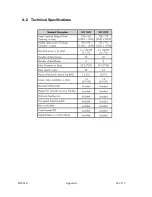
Page 60: ...BJ5 620 Appendix 60 of 73 A 2 Technical Specifications...

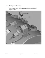
Page 61: ...BJ5 620 Appendix 61 of 73 A 3 Drawings and Diagrams NOTE Please refer to the corresponding spare parts lists in the following section Cutter mounting...

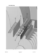
Page 62: ...BJ5 620 Appendix 62 of 73 Bed knife fixing...

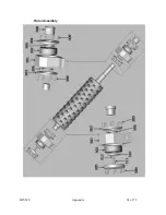
Page 63: ...BJ5 620 Appendix 63 of 73 Rotor Assembly...

Page 64: ...BJ5 620 Appendix 64 of 73 Drive...

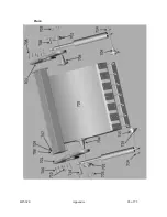
Page 65: ...BJ5 620 Appendix 65 of 73 Ram...

Page 66: ...BJ5 620 Appendix 66 of 73 Ram scraper...

Page 67: ...BJ5 620 Appendix 67 of 73 SXS 1500 2000 Standard Hydraulic Diagram SQ1 SQ2 SQ3 SQ4 9M Pa 9M Pa 15M Pa 125 63 33m l r ec 12m l r ec...

Page 68: ...13 207 4 Lock washer DIN 127 12 300 2 Bearing 301 2 Bearing housing SN236 302 2 Bearing 22236 W33 303 3 Bearing Cover A 304 1 Bearing Cover B 305 0 306 4 Sealing DIN3760 D200 x 230 x 15 307 2 Grease n...

Page 69: ...e cover plate 1 Bed knife cover plate right 604 1 Bed knife cover plate left 605 16 Cover plate Mounting bolt DIN912 M12x30 12 9 606 8 Bed knife adjusting bolt for pulling DIN912 M16x65 12 9 700 1 Ram...

Page 70: ...M16x25 8 8 203 2 Screen adjusting bolt 204 1 Screen support 205 2 Cylinder for screen support opening 63x 35x155 206 4 Washer DIN125 A 13 207 4 Lock washer DIN 127 12 300 2 Bearing 301 2 Bearing housi...

Page 71: ...04 96 Rotor knife holder 505 192 Knife holder fixing bolt DIN912 M10x30 12 9 600 1 Stator knife complete 601 5 Stator knife 399x110x30 602 10 Fixing Bolt DIN 912 M16x60 12 9 603 108 Stator knife adjus...

Page 72: ...r MF 08 1 CLC 3 Electric motor 20HPX4P straight system 380V 1 Qunce 4 Gear pump PVL12 12 33 1 Xinhong 5 Oil cooler JC YL AH1012 1 6 Check valve CRG 03 1 10 1 CLC 7 Check valve CRG 03 1 10 1 7Ocean 8 S...

Page 73: ...lent customer service Service Department Call toll free 8am 5pm CST 800 423 3183 or call 262 641 8610 Emergencies after 5pm CST call 847 439 5655 We have a qualified service department ready to help S...

Reviews: