background image

38

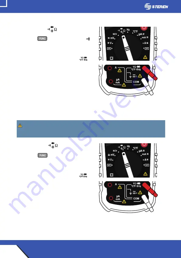
Continuity testing
1. Set the knob in              position.  

2. Press the           button until the symbol  

appears in the screen.

3. Insert the black connector into the COM 

terminal; insert the red connector into          

terminal.

4.Touch with the tips the circuit or wire that 

you want to check.

The resistance value will shown in the 

screen, if the resistance is lower than 30Ω, 

the signal will be audible.

Capacitance measuring

1. Set the knob in              position.  

2. Press the           button until the symbol 

(n F) appears in the screen.

3. Insert the black connector into the COM 

terminal; insert the red connector into          

terminal.

4. Touch the circuit with the tips.

Before to make the measuring, ensure that the capacitor is disconnected from any 

circuit.

Summary of Contents for MUL-605

Page 1: ...1 V0 0 0117v COM CAT III mA V A mA A V mV NCV Hz C F A A C F Hz 1000V MULTIMETRO PROFESIONAL AUTO RANGO USB...

Page 2: ...de operarlo No mida voltajes que excedan 1 000V sobre tierra f sica puede ser riesgoso Tenga mucho cuidado al tomar medidas si los voltajes son mayores a 30 VCA RMS o 60V DC estos voltajes son conside...

Page 3: ...ici n de frecuencia Medici n de temperatura Detecci n de voltaje sin contacto NCV CONEXI N A PC Instalaci n del software Instalaci n del controlador Uso del Software OTRAS FUNCIONES ESPECIFICACIONES D...

Page 4: ...ntacto NCV Indicador LED Pantalla LCD Medici n m xima m nima HOLD retenci n de datos Luz de fondo Perilla de selecci n Terminal Terminal COM Terminal Terminal A Hertz ciclo til Cambio de rango Manual...

Page 5: ...5 Compartimento para bater a Soporte Cubierta Cables de prueba rojo y negro Puntas Conectores Adaptador de temperatura Termopar Cable Mini USB USB...

Page 6: ...e Alterna en mili volts NCV Detecci n de voltaje sin contacto Continuidad Capacitancia Diodos Resistencia Hz Frecuencia C Temperatura en grados cent grados F Temperatura en grados Fahrenheit Corriente...

Page 7: ...apagado 11 Medici n de ciclo til 12 Grados Celsius Fahrenheit 13 Medici n de transistores 14 Unidad de resistencia Kilo ohms mega ohms ohms Unidad de frecuencia Kilo hertz mega hertz hertz 15 Unidad d...

Page 8: ...8 C MO COLOCAR LA BATER A Aseg rese colocar la bater a con la polaridad correcta Si el s mbolo aparece en la pantalla significa que la bater a debe ser reempla zada...

Page 9: ...no intente tomar ningu na medida de tensi n que supere los 1 000 VDC o 750VCA RMS Medici n de voltaje 1 Coloque la perilla de selecci n en la posici n de voltaje 2 Inserte el conector negro en la ter...

Page 10: ...uito 2 Coloque la perilla de selecci n en la posici n de corriente A mA A 3 Inserte el conector negro en la terminal COM Para una medici n inferior a 400 mA inserte el conector rojo en la terminal Par...

Page 11: ...r negro en la terminal COM inserte el conector rojo en la terminal 4 Toque con las puntas el circuito Prueba de diodos Aseg rese de que los circuitos se encuentren sin energ a y los capacitores com pl...

Page 12: ...lor de resistencia se mostrar en la pantalla si la resistencia es menor a 30 la se al ser audible Medici n de capacitancia 1 Coloque la perilla de selecci n en la posici n 2 Presione el bot n hasta qu...

Page 13: ...a negro en la terminal COM inserte el adap tador de temperatura rojo en la terminal 4 Toque con el adaptador la pieza cuya temperatura desea medir mantenga el contacto hasta que la lectura se estabili...

Page 14: ...i tiene energ a el ctrica cable contacto socket etc En caso de detectar presencia de voltaje el indicador LED destellar y el dispositivo emitir una se al audible El dise o del circuito el grosor del a...

Page 15: ...aci n y el funcionamiento pueden variar seg n la versi n del sistema operativo utilizado Instalaci n del software 1 Inserte el CD de instalaci n busque y ejecute el archivo Setup 2 En caso de ser nece...

Page 16: ...blecer la comunicaci n 3 En la carpeta CP210x_Windows_Drivers seleccione el controlador adecuado para las caracter sticas de la PC Haga doble clic para instalarlo Uso del Software 1 Con el mult metro...

Page 17: ...T para comprobar la conexi n y comenzar a visualizar mediciones continuas Seleccione STOP para detener las mediciones Registrar nuevos valores Abrir un archivo Guardar registros Salir Selecci n de ran...

Page 18: ...una vez para retener la lectura en pantalla Luz de fondo Presione para encender la luz de la pantalla Autoapagado Si el mult metro permanece encendido por 15 minutos sin realizar alguna opera ci n en...

Page 19: ...1V 1 8 lectura 0 5 lectura 0 8 lectura Impedancia de entrada 10M M ximo voltaje de entrada 1000V CD Voltaje de Corriente Alterna Rango Resoluci n Precisi n 40mV 60mV 0 01mV 1 0 lectura 400mV 600mV 0 1...

Page 20: ...imo voltaje de entrada 750V CA RMS 0 8 lectura 1 0 lectura 1 0 lectura Corriente CA Rango Resoluci n Precisi n 400 A 600 A 0 1 A 1 0 lectura 4mA 6mA 0 001mA 1 0 lectura 40mA 60mA 0 01mA 400mA 600mA 0...

Page 21: ...tra sobrecarga 250V CD o 250V CA RMS 0 8 lectura Diodos y Continuidad Rango Funci n Voltaje aproximado del diodo La alarma sonar si la resistencia es inferior a 30 Temperatura Rango Resoluci n Precisi...

Page 22: ...1MHz 0 001MHz 1 2 lectura 10MHz 0 01MHz Protecci n contra sobrecarga 250V CD o 250V CA RMS 0 5 lectura Capacitancia Rango Resoluci n Precisi n 10nF 0 01nF 1 0 lectura 100nF 0 1nF 1 0 lectura 1 F 0 00...

Page 23: ...hms Rango de corriente CA 600 uA 10A Rango de corriente CD 600 uA 10 A Rango de Capacitancia 10nF 100mF Rango de frecuencia 10Hz 10MHz Rango de temperatura 0 1 000 C Temperatura de operaci n 0 40 C Te...

Page 24: ...mencionadas posteriormen te ESTA P LIZA NO SE HAR EFECTIVA EN LOS SIGUIENTES CASOS 1 Cuando el producto ha sido utilizado en condiciones distintas a las normales 2 Cuando el producto no ha sido opera...

Page 25: ...25...

Page 26: ...26 V0 0 0117v COM CAT III mA V A mA A V mV NCV Hz C F A A C F Hz 1000V USB PROFESSIONAL DIGITAL MULTITESTER...

Page 27: ...27...

Page 28: ...e meter before to use it Don t measure voltage that exceed 1 000V over fisic ground may be dangerous Be careful when you take measures over 30 VCA RMS o 60V DC this voltages may cause shock hazard Alw...

Page 29: ...y measuring Temperature measuring Non contact voltage detection NCV PC CONNECTION Software installation Driver installation Software use ANOTHER FUNCTIONS MEASURING SPECIFICATIONS Direct current volta...

Page 30: ...tact voltage detector area NCV LED indicator LCD screen max min measuring HOLD Background light Selector knob Terminal COM Terminal Terminal A Terminal Hertz Range change Manual Automatic Function sel...

Page 31: ...31 Battery comparment Support Rubber cover Test cables red and black Tips Connectors Temperature adapter Thermocouple Mini USB USB cable...

Page 32: ...rrent voltage in mili volts NCV Non contact voltage detection Continuity Capacitance Diodes Resistance Hz Frequency C Temperature in centigrades F Temperature in Fahrenheit Direct current and Alternat...

Page 33: ...ue 10 Auto off 11 Duty cycle measuring 12 Degrees Celsius Fahrenheit 13 Transistors measuring 14 Resistence unity Kilo ohms mega ohms ohms Frequency unity Kilo hertz mega hertz hertz 15 Voltage unity...

Page 34: ...34 BATTERY PLACEMENT Ensure that the polarity is right If the symbol appears in the screen means that the battery should be replaced...

Page 35: ...measures higher than 1 000 VDC or 750VAC RMS Voltage measuring 1 Turn the knob to select the voltage type that you want to measure 2 Insert the black connector into the COM terminal insert the red co...

Page 36: ...dischar ge the capacitors of the circuit 2 Adjust the knob to current measuring range A mA A 3 Insert the black connector into the COM terminal To make a measuring under than 400 mA insert the red co...

Page 37: ...l insert the red connector into terminal 4 Touch the circuit with the tips Diode test Be sure that the circuits have not energy and the capacitors are completely dis charged to avoid hazard shock or d...

Page 38: ...u want to check The resistance value will shown in the screen if the resistance is lower than 30 the signal will be audible Capacitance measuring 1 Set the knob in position 2 Press the button until th...

Page 39: ...al insert the red connector into terminal 4 Touch with the adapter the piece where you want to measure the temperature keep the contact until the measure is stabilized Frequency measuring 1 Set the kn...

Page 40: ...ent that you want to check wire contact socket In case of voltage detection the indicator LED will flash and the equipment will emits an audible signal The circuit design the insulation thickness and...

Page 41: ...ndows 10 The install process and the working may vary in accord with the OS version used Software installation 1 Insert the CD of installation search and execute the Setup file 2 If is necessary give...

Page 42: ...to stablish the connection 3 In the folder CP210x_Windows_Drivers select the corresponding driver to the PC featurings Twice click to install it Software use 1 With the multimeter on and connected tw...

Page 43: ...2 Click START to check the connection and visualizing continuous measurements Select STOP to finish the measurements Record new values Open files Save records Exit Range selection Measurement graphic...

Page 44: ...once to hold the reading in the screen Background light Press to turn on the light of the screen Auto off If the multimeter remains turn on for 15 minutes without working it will enter in stand by st...

Page 45: ...V 1000V 1V 1 8 reading 0 5 reading 0 8 reading Input impedance 10M Maximum input voltage 1000V DC Alternating current voltage Range Resolution Accuracy 40mV 60mV 0 01mV 1 0 reading 400mV 600mV 0 1mV 1...

Page 46: ...nce 10M Maximum Input Voltage 750V AC RMS 0 8 reading 1 0 reading 1 0 reading AC Current Range Resolution Accuracy 400 A 600 A 0 1 A 1 0 lectura 4mA 6mA 0 001mA 1 0 lectura 40mA 60mA 0 01mA 400mA 600m...

Page 47: ...otection 250V DC or 250V AC RMS 0 8 reading Diode and continuty Range Function Approx voltage of diode The alarm will emit a sound if the resistance is lower than to 30 Temperature Range Resolution Ac...

Page 48: ...0 1 kHz 1MHz 0 001MHz 1 2 lectura 10MHz 0 01MHz Overload protection 250V DC or 250V AC RMS 0 5 reading Capacitance Range Resolution Accuracy 10nF 0 01nF 1 0 lectura 100nF 0 1nF 1 0 lectura 1 F 0 001...

Page 49: ...60Mohms AC current range 600 uA 10A DC current range 600 uA 10A Capacitance range 10nF 100mF Frequency range 10Hz 10MHz Temperature range 0 1 000 C Operating temperature 0 40 C Storing temperature 10...

Page 50: ...to customer as well as warranty service at any of the addresses mentioned later THIS WARRANTY IS VOID IN THE NEXT CASES If the product has been damaged by an accident acts of God mishandling leaky ba...

Page 51: ...51...

Page 52: ...52...

Reviews: