StepperOnline ISD02 User Manual Download Page 7

I

ntegrated Stepper Motor Driver ISD02/04/08

5

the output current.

For ISD02, a mapped voltage “Va” of 0 - 2V proportionally represents 0 - 2A.

For ISD04, a mapped voltage “Va” of 1. 5 - 4V proportionally represents 1. 5 - 4A.

For ISD08, a mapped voltage “Va” of 1. 5 - 4V proportionally represents 3 - 8A.

Note

:

The driver needs to be powered before mapped voltage “Va” can be measured. (Motor is not required to

be connected at this time. )

DIP1 (on the bottom side DIP switch 2) needs to be turned off to shut down the ACR Function.

After adjustment, user can choose to turn on the DIP1 to enable the automatic current reduction.

Current Adjustment

Trimmer

Before measuring Va:

1) Apply Power

2) Turn off DIP

Voltmeter

Mapped Voltage

Va

Bottom Side

12 ~ 40VDC

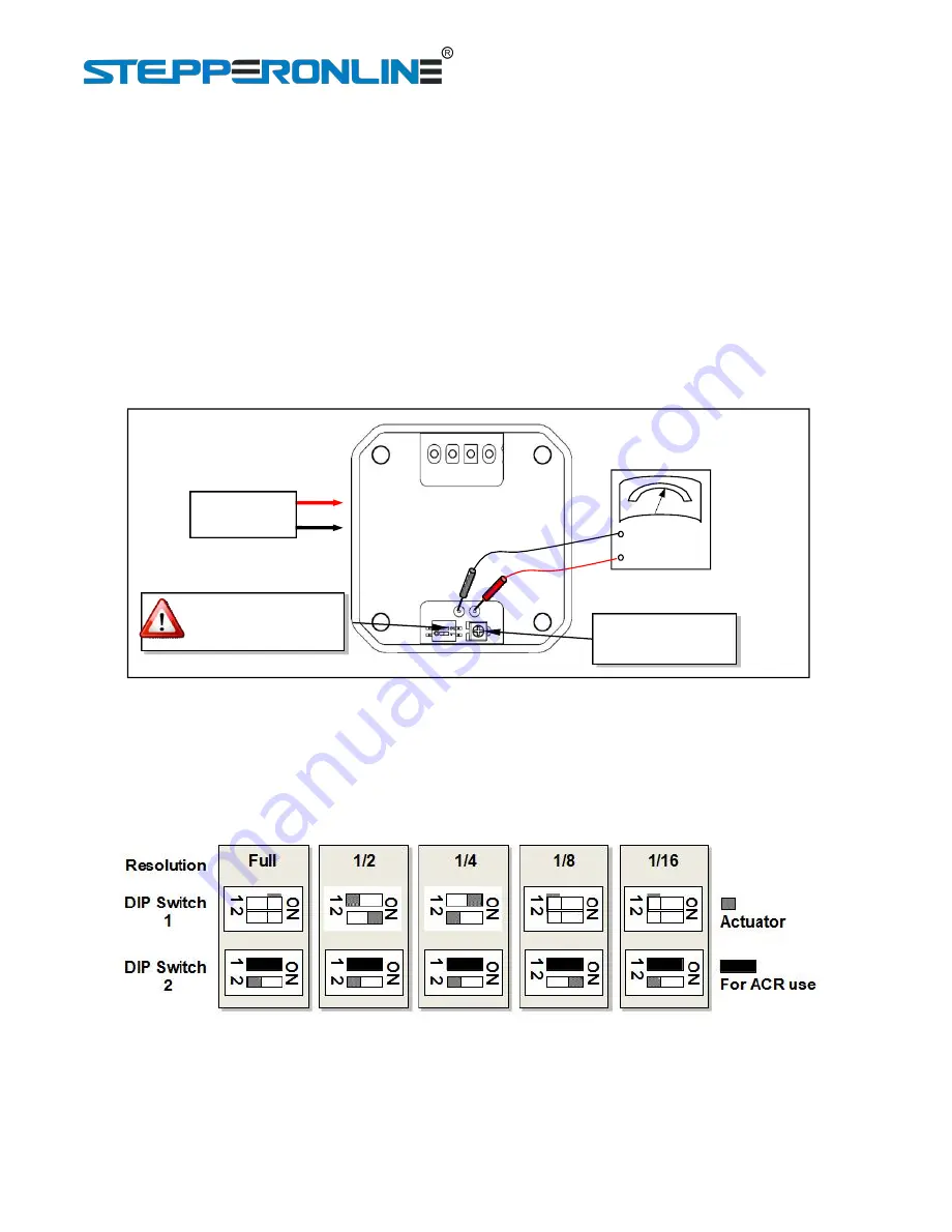
Figure 5: Adjusting the Output Current

5.2 Microstep Resolution

The microstep resolution is set by both DIP switch 1 and DIP switch 2 located at top and bottom side of

the driver as shown in following figure. ISD02/04/08 driver can provide microstep control at 200, 400, 800,

1600, 3200 step resolutions.

Figure 6: Microstep settings

5.3 Power Supply Selection

ISD02/04/08 drivers accept a wide range input voltage from 12 to 40VDC. (ISD02 takes 10 - 28 VDC) In
general, higher supply voltage improves motor performance under high speed situation, but also increases
the power loss and temperature raise.

Summary of Contents for ISD02

Page 1: ...r Driver 7 Zhongke Road Jiangning Nanjing China Tel 0086 2587156578 Web site www omc stepperonline com E Mail sales stepperonline com Designed by STEPPERONLINE 2019 All Rights Reserved Attention Pleas...

Page 2: ...3 Mechanical Specifications 2 3 Pin Assignment and Description 2 3 1 Connector P1 Configurations 3 3 2 Connector P2 Configurations 3 4 Typical application 3 5 Interface 4 5 1 Adjust Output Current 4...

Page 3: ...e motor can also work separately All aluminum precision cast housing sturdy and durable good heat dissipation 0 2A 1 5 4A 3 8A adjustable output current ISD02 ISD04 ISD08 5 selectable microstep soluti...

Page 4: ...line com 2 3 Mechanical Specifications Unit mm Figure 1 Mechanical specifications 3 Pin Assignment and Description The ISD02 04 08 has two connectors P1 P2 P1 is for control signals connections and P2...

Page 5: ...en awaken from shutdown mode wait 1 millisecond before sending pulse 3 2 Connector P2 Configurations Pin Function Description A A Connect to the stepper motor phase A B B Connect to the stepper motor...

Page 6: ...resistor is needed for every terminal to ensure that the current through each emitter does not exceed 20mA Figure 4 Optically Isolated Input Interface Please note in most situations VCC can also be us...

Page 7: ...nable the automatic current reduction Current Adjustment Trimmer Before measuring Va 1 Apply Power 2 Turn off DIP Voltmeter Mapped Voltage Va Bottom Side 12 40VDC Figure 5 Adjusting the Output Current...

Page 8: ...ation 6 1 NEMA 17 Stepper Installation without adapting flange 1 Screw mount ISD controller driver onto the motor 2 Wire the motor leads 6 2 NEMA 23 and Larger Stepper Installation with adapting flang...

Reviews: