User Manual
CL86T (V4.0)
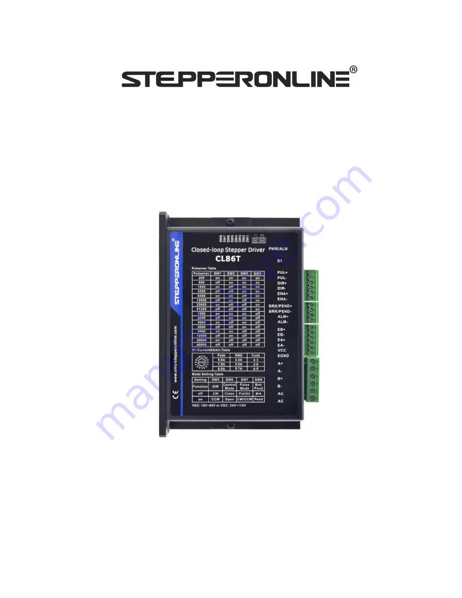
Closed Loop Stepper Driver
Revision 4.0
Record of Revisions
Revision Date
Description of Release
1.00
Aug, 2019
Initial Release
4.00
Oct, 2020
Add rotating switch, 5/24V selector switch, brake output.
Page 1: ...ual CL86T V4 0 Closed Loop Stepper Driver Revision 4 0 Record of Revisions Revision Date Description of Release 1 00 Aug 2019 Initial Release 4 00 Oct 2020 Add rotating switch 5 24V selector switch brake output ...
Page 2: ... 3 3 2 Encoder Signals Input Connector 3 3 3 Motor Connector 4 3 4 LED Status Lights 4 4 Power Supply Selection 4 4 1 Power Supply Sharing 4 4 2 Selecting Supply Voltage 4 5 Switch Configurations 5 5 1 Rotating Switch Configurations 5 5 2 DIP Switch Configurations 5 5 2 1 Micro Step SW1 SW4 5 5 2 2 Mode Setting SW5 SW8 6 6 Typical Connection 6 6 1 Digital Input Connection 6 6 2 Fault Output Connec...
Page 3: ...t by SW8 Over voltage over current protections position following error etc 2 Specifications 2 1 Electrical Specifications Parameters Min Typical Max Unit Peak Current 5 6A RMS 4A 7A RMS 5A 8A RMS 5 7A A Operating Voltage 18 24 80 110 VAC VDC Logic input signal current 7 10 20 mA High speed pulse input frequency 5V 0 500 kHz Pulse input frequency 24V 0 200 kHz Input signal voltage 5 24 VDC Logic c...
Page 4: ...cations 2 4 Heat Dissipation CL86T V4 0 reliable working temperature should be no more than 40 109 F It is recommended to mount the drive vertically to maximize heat dissipation Mount a cooling fan nearby if necessary If multiple CL86T V4 0 drives are installed it is suggested to keep a minimal 30mm 12 inches between two of them ...
Page 5: ...PUL CW I DIR CCW I DIR CCW I ENA I Enable Signals Optional 1 Effective high level is 3 5 24V Effective low level is 0 0 5V connection 2 ENA signal requires advance DIR signal minimum 200ms in single pulse mode default no connection ENA I BRK PEND O Select brake output or pend output by switch 8 default as brake output Max 30VDC 100mA BRK PEND O ALM O Max 30VDC 100mA ALM O Notes 1 Shielding control...
Page 6: ... to be achieved at the price of more noise and heating If the motion speed requirement is low it s better to use lower supply voltage to decrease noise heating and improve reliability 4 1 Power Supply Sharing Multiple CL86T V4 0 drives can share one power supply to reduce cost if that power supply has enough power capacity To avoid cross interference connect each stepper drive directly to the shar...
Page 7: ... 16 25 25 3 16 50 15 7 0A 4 0 25 25 5 0 50 15 6 0 100 5 7 16 25 25 8 16 50 15 9 16 100 5 8 0A A 0 25 25 B 0 50 15 C 0 100 5 D 16 25 25 E 16 50 15 F 16 100 5 5 2 DIP Switch Configurations The 8 bit is located on the side and used to configure settings of micro step resolution output current and motor standstill current as shown below Figure 2 DIP switches 5 2 1 Micro Step SW1 SW4 Each CL86T V4 0 ha...
Page 8: ...f off off 200 40000 off off off off 5 2 2 Mode Setting SW5 SW8 Function ON OFF SW5 Rotation Direction CW clockwise CCW counterclockwise SW6 Control Mode Open loop control Closed loop control SW7 Pulse Mode CW CCW double pulse PUL DIR single pulse SW8 Brake pend Pend output Brake output 6 Typical Connection 6 1 Digital Input Connection The CL86T V4 0 can accept can accept differential or single end...
Page 9: ...protection happens CL86T V4 0 red status LED light will blink and the impedance state between ALM and ALM will change from low to high or high to low depending on configuration and can thus be detected Fault output connection is optional and it can be connected either in sinking or sourcing 6 3 Brake Output Connection This drive has a special brake output it needs to drive the motor brake with a r...
Page 10: ... shown as following diagram Figure 8 Sequence chart of control signals Remark a t1 ENA must be ahead of DIR by at least 200ms Usually ENA and ENA are NC not connected See Connector P1 Configurations for more information b t2 DIR must be ahead of PUL effective edge by 2us to ensure correct direction c t3 Pulse width not less than 1us d t4 Low level width not less than 1us e Duty cycle of PUL signal...
Page 11: ... sale 7 0 2S 0 3S 5S Position following error a Set SW6 to ON to make motor run in open loop mode If alarm disappears it means encoder wiring error b Motor torque is not enough or motor speed is too high Always PCB board is burned out Restart the power supply if the drive is still alarm please contact after sale When above protections are active the motor shaft will be free or the red LED blinks R...
Page 12: ...control signal is within 7 16mA Control signal is interfered Don t tie the control signal cable with power cable together Wrong motor connection Refer to user manual of drive and motor datasheet Something wrong with motor coil Check the motor is normal Motor stalls during acceleration Current setting is too small Choose another power supply with lager power or increase the output current of drive ...