-9-
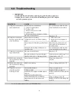
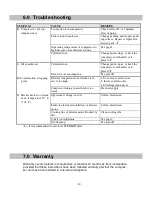
6.0 Trouble shooting
SYMTOM
CAUSE
REMEDY
F.
Compressor can not at-
tain the required working
pressure.
Inlet underdimensioned, e.g. inlet pipe
between inlet and compressor.
Dimension inlet pipe correctly -
larger fresh air intake.
Pressure gauge defective.
Replace it.
Unit too small in proportion to air con-
sumption.
Connect further capacity.
Compressor worn
Have compressor overhauled, or
replace it.
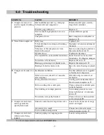
G. Noise from compressor. Bolts loose
Tighten bolts.
V-belt, flywheel or cooling coil touching
belt guard.
Find place of contact and remedy
the fault.
Vibrations of the compressor is trans-
ferred to the air net
Insert a connecting hose between
the unit and the air net.
Flywheel loose.
Tighten the flywheel.
Unit installed on an unsuitable foundation. Move the unit to a more solid
foundation - fit vibration dampers.
Non-return valve defective.
Replace the valve.
Bearings, piston rings or cylinder worn.
Replace the worn parts.
Bearings of electric motor worn
Have the motor bearings replaced.
H. Compressor becomes too
hot.
Insufficient ventilation.
See that sufficient air is supplied
to flywheel of compressor.
Oil level too low (check 2 or 3 minutes
after stopping).
Fill with oil up to centre of oil
level glass.
Wrong direction of rotation.
Cooling air from flywheel must
blow towards compressor.
Dirt on cooling ribs or inlet grate.
Clean cooling ribs and inlet grate
in the belt guard.
Unit working at too high pressure.
Set working pressure in accor-
dance with factory’s recomman-
dation.
Non-return valve partly blocked.
Clean or thaw out the non-return
valve (see point B)
I.
Compressor unit starts
and stops more fre-
quently than usual.
Leaks in control unit or inspection cover. Locate leaks (by means of soapy
water) and repair.
Air receiver too small.
Connect an extra air receiver.
Too low differential pressure.
Adjust pressure switch.
J.
Compressor unit starts
when no air is being
tapped.
Leaks in piping or at tapping points.
Locate and repair leaks.
= It is recommended to call local STENHØJ fitter.
Summary of Contents for T63514
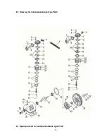
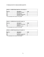
Page 14: ... 14 8 2 Drawing for compressorblock type PL50 ...
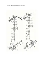
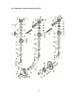
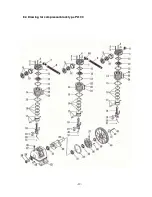
Page 16: ... 16 8 3 Drawing for compressorblock type PL75 ...
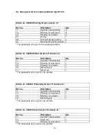
Page 19: ... 19 8 4 Drawing for compressorblock type PL100 ...
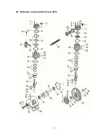
Page 21: ... 21 8 5 Drawing for compressorblock type TE50 ...
Page 24: ... 24 8 6 Drawing for compressorblock type TE75 ...
Page 27: ... 27 8 7 Drawing for compressorblock type TE100 ...
Page 30: ... 30 8 8 Drawing for compressorblock type PE 50B ...


