background image

22

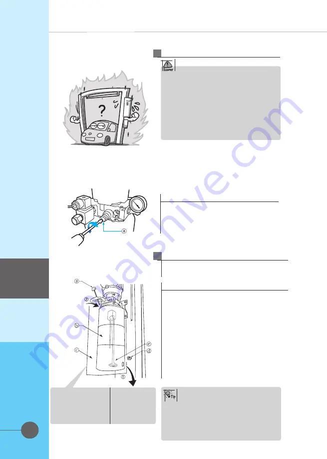
If machine can't lift 4,000㎏.
① Put the pressure gauge.
② Open the cap of relief valve and adjust

put up button.

The power pack pressure is set by the 

factory in accordance with the lift's 

maximum rated capacity. The 

pressure regulator is sealed by the 

factory and should not be tampered 

with. Excessive adjustment can result in 

serious damage. If the hoist fails to 

raise the maximum rated load, contact 

your approved maintenance engineer.

Power pack pressure

2

Standard pressure settings model

SB40

14 Mpa

Do this action

Maintenance

ⓐ Filter cap and dipstick
ⓑ Oil tank
ⓒ Drain plug
ⓓ Pump filter

 Oil filter

② 

Oil discharge

Oil change procedure

· Remove the cover of the hydraulic unit.

· Remove the oil filter cap and dipstick.

Carefully remove the oil drain plug and allow the oil 

to discharge into a suitable container.

· Refit the drain plug and tighten

· Refill the oil tank with new oil

· Check with the dipstick that the level is

correct ; raise and lower the hoist and recheck

that the level is still correct. If not, top up with oil.

· Refit the cover 

Oil change

3

Oil should be changed 2 months after 
installation and thereafter annually.

At the annual oil change, after having 
drained the oil tank, remove the oil 
tank from the pump and check the 
condition of the pump filter. Clean or 
replace as necessary.
Replace tank and follow the above 
procedure. 

Summary of Contents for MOLNAR BRADBURY SB40

Page 1: ...nual before you get started You must read and understand the precautions for safety purposes and any damages that may occur to your property Installation Operation Maintenance Manual SB40 2POSTHOIST SB40 Updated 19 05 21 ...

Page 2: ...d in December of 2018 The Specifications images are subject to change without prior notice images and sketches are for illustration purposes only This Manual is for model SB40 Design Registration V1803235 Vehicle Hoist Model No SB40 As for the assurance of safety in design and construction of car hoist read this Manual first Please make sure that this Manual is delivered to end users for their imp...

Page 3: ...Place of Installation Layout 10 10 11 Safety Danger Warning Caution 8 8 Operation Check Points Before Operation Operation Operation Procedures of Each Part 16 16 17 28 Maintenance Maintenance Troubleshooting Check List and Periodic Maintenance Part List 20 20 23 24 Introduction Safety Installation Operation Mainternance Part List TABLE OF CONTENTS ...

Page 4: ...ection bar Industrial direct drive cylinder Arm lock gear Introduction Door protection rubber Upper limit protection bar A limit bar prevents the vehicle from being lifted too high This feature effectively protects taller vehicles from being damaged ...

Page 5: ...Powerful arm lock gear At the bottom position the gears are unlocked to allow arm adjustment When the hoist is raised the gears are automatically locked ensuring complete safety Unlocked Locked Introduction Door protection rubber Safety locker Vehicle door protect during working Safety locker system Two individual cylinders ensure reliability ...

Page 6: ...st Cylinder Locker cover Locker inside Short arm 1 2 3 4 5 6 7 8 9 10 11 12 13 Drive post Power Pack Carriage Door protection rubber pad Long arm Pick up pad 1 2 3 4 5 6 7 12 8 9 10 11 Part Descriptions Introduction 13 Top limit touch bar ...

Page 7: ...IN HEIGHT STROKE LIFTING TIME LOWERING TIME POWER MOTOR NET WEIGHT SB40 4 000 Kg 14 Mpa 1 895 1 940 mm 95 140 mm 1 800 mm Approx 45 60 sec Approx 35 50 sec 3Ph 2 2Kw 2Poles 415V 50Hz 700 kg Specification Introduction 1Ph 2 2Kw 2Poles 240V 50Hz ...

Page 8: ...injuries Evacuate to a safe place instantly in the event that the vehicle tips It may cause severe injuries Do not overload the rated capacity It may cause severe injuries Fail to follow the instructions can lead to a critical accident involving your life Make sure you follow the instructions Only trained personnel may operate the equipment Inexperience can cause accidents Position the vehicle to ...

Page 9: ... carriages Before going under the hoist make sure that the safety pawls are engaged To avoid being electrocuted disconnect the main power before opening the control panel Do not modify the control panel or the safety functions as this may impair their function Do not rock the vehicle when lifted Do not use a high pressure cleaner as the vehicle lower part Read and fully understand the manual befor...

Page 10: ...sure that the anchor is secure the hole for an anchor bolt must be more than 2 3 of the bolt length Installation site To maintain the warranty the hoist is intended for indoor installation only In the event that it is installed outside it should be protected from snow and rain Outdoor installation makes the warranty invalid Onlycompetent techniciansshallinstall thehoist otherwisea failuremay occur...

Page 11: ... 140 Place of Installation Layout Check points before selecting the place of installation Distance from wall or any fixed object Drive on direction Positions of power post and slave post Ceiling height and height of cross member Installation 3750 3560 2856 ...

Page 12: ...0N m 100N m Before securing with anchor bolts ensure that the post is vertical in both directions Vertical balance Check that the post is vertical in both directions and adjust by means of the shim plates provided Fix by anchor bolts Adjusting verticality Fixing the post 1 2 Connection of the hydraulic hose Before setting up the post connect the hydraulic hose and tighten it with a 19 17mm spanner...

Page 13: ...ate of the post when the hoist descends and then tighten This cable until both carriages lest on lie base plates simultaneously Adjusting the cables How to check the tuning adjustment Check with naked eyes that the bottom post reached simultaneously see above Check with ears Check the sound of the parking pawls engaging in each slat during ascent The clicks should be simultaneously if not tighten ...

Page 14: ...14 14 Installation Hydraulic Diagram LOWERING VALVE 9 16 18 UNF ...

Page 15: ...15 Installation Electrical Diagram ...

Page 16: ...the ascent and descent lever operate correctly Hydraulic Check Check that there are no hydraulic leaks from either cylinders pipes or hose joints Mechanical Check Check the tightness of all nuts bolts etc Exterior Check Check the exterior of the hoist to ensure that there is no obvious damage Cleanliness Check every day that the hoist and the work area are clean and free from debris or obstruction...

Page 17: ...s center of gravity in line with the 2 posts Vehicle entry 3 Raise the hoist approx 50mm and check visually and mechanically to ensure that each arm lock is firmly engaged Check the arm locks 5 Swing in the 4 arms under the vehicle and adjust the length of each arm so that the pick up pad is directly underneath the pick point recommended by the vehicle manufacturer Each pad is fitted with telescop...

Page 18: ...ased automatically Release the pick up pads from the pick up points by screwing down the telescopic threads Swing the arms from under the vehicle to the straight ahead position and remove the vehicle Vehicle repairs 7 Operation Procedures of Each Part Arm Lock Operation When the carriages go up the arm locks are engaged automatically Ensure that the gears controlling the locks are in mesh i e full...

Page 19: ...mm ⓓ Dia 120mm 26K Arm 2 section telescopic arm ⓐ 920 mm ⓑ 1400 mm 3 section telescopic arm ⓐ 600 mm ⓑ 850 mm ⓒ 1075 mm The height of the pad can be adjusted 3 stages as shown below 3 stage telescopic pad adjustment 2 Operation ...

Page 20: ...ice usage Clean the arm lock gears and surroundings lubricate the gear teeth and the release mechanisms Clean the safety lock pawls and lubricate the axles Synchronization Cable Adjustment Check that both carriages are fully parked on the base of the hoist at the bottom position Raise the hoist without load and listen to the audible clicks of the 2 lock pawls The synchronization of the 2 carriages...

Page 21: ...21 Maintenance Arms Once a week check the condition of each arm by sliding each section to its fully extended position and ensure that the arm stop is working correctly ...

Page 22: ... Drain plug ⓓ Pump filter Oil filter Oil discharge Oil change procedure Remove the cover of the hydraulic unit Remove the oil filter cap and dipstick Carefully remove the oil drain plug and allow the oil to discharge into a suitable container Refit the drain plug and tighten Refill the oil tank with new oil Check with the dipstick that the level is correct raise and lower the hoist and recheck tha...

Page 23: ...23 Maintenance Troubleshooting 2 3 4 5 2 3 4 5 ...

Page 24: ...24 Check list and periodic maintenance Maintenance Stopper screws for the sliding arms worn and deformation only when necessory only when necessory only when necessory only when necessory ...

Page 25: ...PART LIST 25 SB40 This manual was prepared in December of 2018 The Specifications images are subject to change without prior notice images and sketches are for illustration purposes only ...

Page 26: ... Post extension Slave post Cylinder Locker cover Locker inside Short arm 1 2 3 4 5 6 7 8 9 10 11 12 13 Drive post Power Pack Carriage Door protection rubber pad Long arm Pick up pad Top limit touch bar 1 2 3 4 5 6 7 12 8 9 10 11 13 ...

Page 27: ...0 MP 9 10 E Ring SB40 MP 10 11 Lever Connector SB40 MP 11 12 Wrench Bolt SB40 MP 12 13 Lock Spacer SB40 MP 13 14 Lock Block SB40 MP 14 15 Spring Pin SB40 MP 15 17 Lock Wire Roller SB40 MP 17 18 SB40 MP 18L 23 Wire Roller SB40 MP 23 24 Power Unit SB40 MP 24 25 Anit Vibrated Rubber SB40 MP 25 26 Up Limit Switch SB40 MP 26 27 Hexa Nut SB40 MP 27 28 Flat Washer SB40 MP 28 29 Hexa Bolt SB40 MP 29 30 Up...

Page 28: ...1 12 Wrench Bolt M10 SB40 CC 12 13 Hose Adapter SB40 CC 13 14 Cylinder Tube SB40 CC 14 15 D U Bearing SB40 CC 15 16 Head Cover SB40 CC 16 17 Dust Seal SB40 CC 17 18 Wrench Bolt M10 SB40 CC 18 19 Spring Washer SB40 CC 19 20 Flat Washer M10 SB40 CC 20 25 22 21 23 24 13 21 21 Dotty washer SB40 CC 21 22 Flow restricting valve SB40 CC 22 23 Spring SB40 CC 23 24 Housing SB40 CC 24 25 SB40 CC 25 Banjo fi...

Page 29: ...0 SP 8 9 Large Arm Lock Gear SB40 SP 9 10 Small Arm Lock Gear SB40 SP 10 11 Arm Lock Spring SB40 SP 11 12 Gear Shaft SB40 SP 12 13 Spring Pin SB40 SP 13 14 Wrench Bolt SB40 SP 14 15 Hex Bolt SB40 SP 15 16 Flat Washer SB40 SP 16 17 Arm Support Rubber SB40 SP 17 18 Arm Supporter SB40 SP 18 19 Arm and Supporter SB40 SP 19 20 Spring Washer SB40 SP 20 21 Lock Gear Spacer SB40 SP 21 22 Split Pin SB40 SP...

Page 30: ...e Roller Shaft SB40 CB 2 3 Snap Ring SB40 CB 3 4 Wire Roller 5 Wire Roller Spacer SB40 CB 5 6 Limit Switch SB40 CB 6 7 E Ring SB40 CB 7 8 Limit Switch Fixture SB40 CB 8 9 Upper Limit Touch Bar SB40 CB 9 10 Hexa Bolt SB40 CB 10 11 Hexa Nut SB40 CB 11 12 Flat Washer SB40 CB 12 SB40 MP 23 ...

Page 31: ...6 Seal ring SB40 M 6 7 Bolt for block SB40 M 7 8 Pump SB40 M 8 9 Bolt for pump SB40 M 9 10 Suction pipe SB40 M 10 11 Filter SB40 M 11 12 Screw for tank SB40 M 12 13 Fuel tank SB40 M 13 14 Oil return pipe SB40 M 14 15 Cusion valve SB40 M 15 16 Throttle valve SB40 M 16 17 Lowering handle valve SB40 M 17 18 One way valve SB40 M 18 19 Pushbutton box SB40 M 19 31 ...

Page 32: ...Address 3 Graham Street Export Park South Australia 5950 Ph Fax Email Web 61 08 8234 3611 61 08 8234 4322 sales molnarhoists com au www molnarhoists com au ...

Reviews: