11
2.
The specifications for the STEM Board microprocessor are:
Microcontroller
ATmega328
Operating Voltage
5V
Input Voltage (recommended)
7 – 12V
Input Voltage (limits)
6 – 20V
Analog Input Pins
6
Digital I/O Pins
14 (of which 6 provide PWM output)
DC Current for 3.3V Pin
50 mA
Flash Memory
32 KB of which 0.5 KB used by bootloader
SRAM
2 KB
EEPROM
1 KB
Clock Speed
16 MHz
Digital Input/Output
1.
After plugging the STEM Board microprocessor into your PC using the USB connector, you
should notice that the green LED power light is turned on. You do not need to plug in the 9-volt
battery at this point as the board is now powered from the USB port.
2.
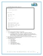
If everything looks good, enter and run the program: led_01.ino, as shown in Figure 2.2. The LED
on your STEM Board microprocessor for channel 13 (as shown in Figure 2.2) should be flashing.
Figure 2.2: Program – led_01.ino
3.
As before, the program consists of two separate functions,
setup ()
and
loop ()
a.
Note:
In the setup function, digital pin 13 is defined to an output pin.
Again, the loop function is the main program. The statement
digitalWrite (13,HIGH
);
is a function call to the digitalWrite. The first parameter is the pin number, as shown
at the top row of the STEM board microprocessor in Figure 2.1. The second
parameter,
HIGH
, is a predefined constant for 1. Likewise,
LOW
is a predefined
constant for 0.
Note that C is case-sensitive. Typing in
High
instead of
HIGH
will cause an error. That
is why
HIGH
is blue and
High
is black, reminding you that you are using predefined
Summary of Contents for Pi-Bot v2.00
Page 67: ...67 Figure 6 15 ...
Page 78: ...78 UltraSonicSensorTestwithLED Program ...
Page 80: ...80 ObstacleAvoidance Program ...
Page 82: ...82 ObstacleAvoidancewithLED Program ...
Page 83: ...83 ObstacleAvoidancewithLED Program CONTINUED ...
Page 90: ...90 Download and run the following program LineFollowing Program ...
Page 91: ...91 LineFollowing Program CONTINUED ...
Page 94: ...94 AdvancedLineFollowing Program CONTINUED ...
Page 95: ...95 AdvancedLineFollowing Program CONTINUED ...
Page 96: ...96 AdvancedLineFollowing Program CONTINUED ...
Page 110: ...Appendix B Complete Pi Bot Wiring Schematic ...


