


114
STEL s.r.l. – Via del Progresso n° 59 – 36020
Loc. Castegnero (VICENZA) - ITALY
TEL. +39 444 639525 (central.) – +39 444 639682 (comm.)
FAX +39 444 639641 – E-mail: stel @ stelgroup.it
http: www.stelgroup.it
MAX dp 171-201C
COD. 6910700020
ÍNDICE GENERAL
1.0 SEGURIDAD
1.1
ADVERTENCIAS
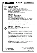
1.2 INSTRUCCIONES PARA LA SEGURIDAD
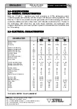
2.0 ESPECIFICACIONES
2.1
CARACTERÍSTICAS
GENERALES
2.2 CARACTERÍSTICAS ELÉCTRICAS
3.0 RECEPCIÓN
3.1 RECEPCIÓN DEL MATERIAL
3.2
RECLAMACIONES
4.0 CONEXIÓN
4.1 CONEXIÓN PRIMARIA Y ACOPLAMIENTO
4.2 PUESTA A TIERRA
5.0 PUESTA EN SERVICIO
5.1 MANDOS DEL PANEL FRONTAL
5.2
DESCRIPCIÓN
SÍMBOLOS DE LA PLACA DE DATOS
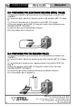
5.3 DISPOSICIÓN DE SOLDADURA POR ELECTRODOS (MMA)
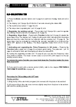
5.4 DISPOSICIÓN DE SOLDAURA TIG
6.0 SOLDADURA POR ELECTRODO (MMA)
6.1 PROCEDIMIENTOS DE LA SOLDADURA POR ELECTRODO
6.2 FASES DE LA SOLDADURA POR ELECTRODO
7.0 SOLDADURA TIG
7.1 PROCEDIMIENTOS DE LA SOLDADURA TIG
7.2 FASES DE LA SOLDADURA TIG
8.0 DESCRIPCIÓN DE LAS FUNCIONES DE SOLDADURA
8.1 SOLDADURA POR ELECTRODO
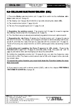
8.2 SOLDADURA POR ELECTRODO CELULÓSICO (CEL)
8.3 SOLDADURA TIG
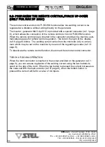
9.0 PREDISPOSICIÓN DEL MANDO A DISTANCIA/SOPLETE UP-DOWN
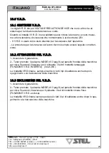
10.0 V.R.D.
10.1 GESTIÓN DEL V.R.D.
10.2 ACTIVACIÓN DEL V.R.D.
10.3 DESHABILITACIÓN DEL V.R.D.
11.0 FIGURAS
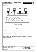
11.1 DISTANCIAS POSTERIORES Y LATERALES A MANTENER DURANTE LA SOLDADURA
11.2 SEÑALES DE SEGURIDAD
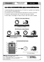
11.3 CICLO DE INTERMITENCIA Y SOBRETEMPERATURA
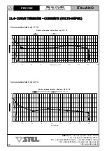
11.4 CURVAS DE TENSIÓN Y DE CORRIENTE
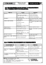
12.0 INCONVENIENTIES DE SOLDADURA Y DE FUNCIONAMIENTO
12.1 POSIBLES DEFECTOS DE SOLDADURA
12.2 POSIBLES INCONVENIENTES DE FUNCIONAMIENTO
12.3
MANTENIMIENTO
ORDINARIO
13.0 LISTA DE COMPONENTES Y DIBUJOS DE DESPIECE
13.1 LISTA DE COMPONENTES
13.2 DIBUJO DE DESPIECE MAX dp 171/201C
14.0 ESQUEMAS ELÉCTRICOS
14.1 ESQUEMA ELÉCTRICO GENERAL MAX dp 171C
14.2 ESQUEMA ELÉCTRICO GENERAL MAX dp 201C
14.3 ESQUEMA CONEXION DE ALFILERES DE LAS UNIONES
ÍNDICE
ESPAÑOL
35
MAX dp 171-201C
COD. 6910700020
STEL s.r.l. – Via del Progresso n° 59 – 36020
Loc. Castegnero (VICENZA) - ITALY
TEL. +39 444 639525 (central.) – +39 444 639682 (comm.)
FAX +39 444 639641 – E-mail: stel @ stelgroup.it
http: www.stelgroup.it
- Ensure that the fan does not send deposits or dust into the machine.
- Avoid impacts, rubbing, and - absolutely - exposure to dripping water, excessive heat sources, or any
abnormal situations.
MAINS VOLTAGE
The generator works at mains voltages differing by 15% from the rated mains value (for example: rated
voltage 230V, minimum voltage 195V, maximum voltage 265V).
SUPPLY BY GENERATING SET
The generator is designed to work supplied by generating sets.
1) - The 230V a.c. auxiliary socket must be able to supply suitable power indicated in the section
(electrical characteristics on page 5).
2) - The auxiliary socket of the generating set must also satisfy the following conditions:
- peak voltage of the a.c. wave less than 423V a.c.
- frequency of the a.c. wave between 50 and 60Hz.
- RMS voltage of the a.c. wave higher than 180V a.c.
It is important for the generating set to satisfy the conditions listed in points 1 and 2.
It is advised not to use this machine with generating sets that do not fulfil these conditions because it
might be damaged.
CONNECTION
- Before making any electrical connections between the current generator and the line switch, make
sure that the switch is turned off.
- The distribution panel must comply with the regulations in force in the country of use ( ).
- The mains system must be of the industrial type.
- Provide a special socket which can accept leads with section 2.5 mm² and 4mm².
- For longer cables, increase the lead section accordingly.
- Upstream, the special mains socket must have an adequate switch with delayed fuses.
4.2– EARTHING
- To ensure user protection the welding machine must absolutely be correctly
connected to the earth system (INTERNATIONAL SAFETY REGULATIONS).
- It is indispensable to provide good earthing by means of the yellow-green lead in
the power cable, in order to avoid discharges due to accidental contacts with
earthed objects.
- The chassis (which is conductive) is electrically connected with the earth lead; if
the equipment is not suitably connected to earth it may cause electric shocks which
are dangerous for the user.
MODEL
VOLTAGE/PHASES
DELAYED FUSE
MAX dp 171C 230V 1F
MAX dp 201C 230V 1F
1 phase 230V
1 phase 230V
16 A
20 A
ENGLISH
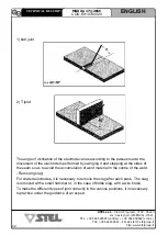
TECHNICAL DECRIPTION
Summary of Contents for MAX dp 171C
Page 152: ......


