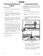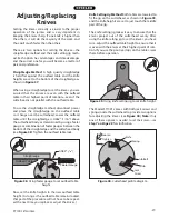
-14-
ST1001 6" Jointer
Components and Hardware Needed:
Qty
Dust Chute Cover ................................................................. 1
Dust Port .................................................................................. 1
Wing Screws ........................................................................... 2
If you do not connect your machine to a dust collec-
tion system, do not install the dust port. Instead, just
allow the dust chute to direct the wood shavings into
a box or trash container. If the dust port is installed
and a dust collector is not used, dust will build up
inside the jointer and eventually be thrown out from
the cutterhead opening.
Recommended CFM at Dust Port:
400 CFM
Do not confuse this CFM recommendation with the rat-
ing of the dust collector. To determine the CFM at the
dust port, you must take into account the CFM rating of
the dust collector, the length of hose between the dust
collector and the machine, the amount of branches or
wyes, and the amount of other open lines throughout
the system. Explaining this calculation is beyond the
scope of this manual. If you are unsure of your system,
consult an expert or buy a "how-to" book.
To install the dust chute and port:
1.
Install the dust chute cover by inserting the
guide posts into the dust chute/motor mount.
— If you are not installing the dust port,
secure the dust chute with the wing screws.
Otherwise, proceed to the next step.
2.
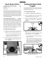
Place the dust port over the bottom of the dust
chute, and attach it with the wing screws, as
shown in
Figure 18
.
Dust Chute & Port
Figure 18.
Dust port installed.
Wing Screws
Setting Outfeed Table
Height
Figure 19.
Cutterhead knife at top dead center.
��������
������
The outfeed table MUST be even with the knives at
top dead center (TDC) or the workpiece cannot be
fed across the jointer safely.
To set the outfeed table height:
1.
DISCONNECT JOINTER FROM POWER SOURCE!
2.
Place a straightedge across the length of the
outfeed table and over the cutterhead
.
3.
Rotate the cutterhead pulley until one of the
knives is at top dead center, as illustrated in
Figure 19
.
When correctly set, the knife will barely touch
the straightedge, as shown in
Figure 20
.
—If your outfeed table is correctly set, no adjust-
ments are necessary.
—If the knife lifts the straightedge off the table
or the knife is below the straightedge, then
adjust the height of the outfeed table to just
touch the knife at TDC. Remember to lock the
outfeed table in place after adjusting.
Figure 20.
Using a straightedge to align outfeed
table height with knife at TDC.
������������
�������
������
Summary of Contents for ST1001
Page 2: ......
Page 36: ...34 ST1001 6 Jointer ST1001 Wiring Diagram...
Page 37: ...ST1001 6 Jointer 35 Jointer Breakdown...
Page 39: ...ST1001 6 Jointer 37 Fence Breakdown...
Page 44: ......
Page 47: ......
Page 48: ......

