background image

Page  1  of  24

939503312  R ev. A

T o p o

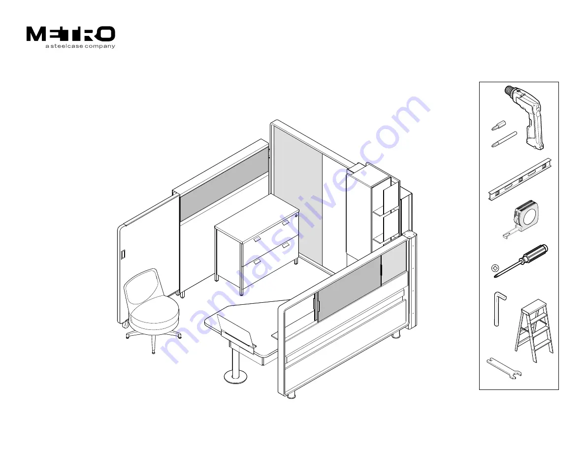
  O p e n   P la n   A s s e m b ly   D ir e c t io n s

®

2

3

4

B it E xtension

Combo Wrench

© 2007 Coalesse - Metro, Grand R apids, MI, USA.  

Please feel free to contact
Metro Customer Service with 
any questions or concerns:
866.645.6953

www.metrofurniture.com

Summary of Contents for Metro Topo

Page 1: ...o O p e n P la n A s s e m b ly D ire c tions 2 3 4 Bit Extension Combo Wrench 2007 Coalesse Metro Grand Rapids MI USA Please feel free to contact Metro Customer Service with any questions or concerns 866 645 6953 www metrofurniture com ...

Page 2: ...tallation Connector Post A page 5 B page 9 Flex fit Wall page 5 Desk Loop page 6 Do not disassemble for transporting purposes Loop to post Connector page 6 Flex fit Wall Loop w Scrim page 7 Return Wall Frame w Roller Screen page 10 Desktop page 16 Overhead Tower page 21 Pedestal page 18 Baseboard Utility page 5 Optional Sliding Marker and Tack Panel assembly direction TOPO 003 A B ...

Page 3: ...le page 13 Wire Manager page 13 Desk Loop Sill page 13 Desk Loop Scrim page 14 Desk Loop Sliding Panel page 15 Tether Bracket page 16 Adjustable Column Leg page 16 Hyper Glide page 17 Panel Rollers page 15 Connector Brackets page 18 Finish Top Cap page 22 Optional Lower Mod Panel page 23 Fold Scrim page 23 Optional Upper Mod Panel page 24 Wire Management Tray page 19 Upper Lower LH shown LH shown ...

Page 4: ...ays the same the round modular connector that protrudes from each side of the baseboard utility must always be under the pocket segment of the flex fit wall The reason for this is simple the modular connector referred to is the power source for the desktop utility and desktops are always next to the pocket segment of the flex fit wall There are two possible orientations of the flex fit wall relati...

Page 5: ...nnector post over excess flex conduit in baseboard utility if applicable 4 Loosely attach connector post to flex fit wall frame 5 Install top cap of connector post 3 2 4 4 5 16 24 x 3 8 hex head 4 2 x 2 square washers Connector Post A Flex fit wall frame Baseboard Utility will not be shown in this direction again for more information refer to installation instruction No 42651 Opening allows excess...

Page 6: ...E CAREFUL NOT TO SCRATCH LOOP EXTRUSION SURFACE 4 Loosely pre assemble desk loop to connector post by lightly tightening fasteners in loop to post connector 5 Level desk loop and flex fit wall 6 Tighten fasteners on loop to post connector and flex fit wall frame BE CAREFUL NOT TO OVERTIGHTEN 1 7 screws 1 4 28 x 3 4 socket head cap 2 Fasteners should face out away from inside corner Loop to post co...

Page 7: ...ns top and bottom into frame 8 Install tolerence extrusion in center track of bottom loop HANDLE PARTS CAREFULLY THEY MAY BE FRAGILE DURING INSTALLATION Top Loop Bottom Loop Flex fit wall loops Tolerence extrusion 7 8 END VIEW showing 3 preinstalled inner extrusions ...

Page 8: ...sert corner casting into vertical loop at top and bottom then tighten 2 set screws at each corner 11 Fit vertical loop extrusion to horizontal loop extrusion and secure with set screws 4 places 9 10 10 11 Fabric scrim Corner casting Vertical loop Slide loop extrusion and scrim in all the way for now END VIEW Insert top of scrim into middle extrusion 9 ...

Page 9: ... screws 14 Install a connector post with loop to post connectors onto vertical loop refer to page 4 15 Level assembly and secure by tightening fasteners on loop to post connector DO NOT OVERTIGHTEN Finger tighten Loop bracket 12 15 13 4 1 4 20 x 1 1 2 thumb screws plastic head Make sure connector post is plumb before tightening 13 13 14 Loop to post connectors Connector Post B ...

Page 10: ...ion 5 Remove V track 6 Disconnect the back vertical rail of rolling panel by removing the bolt above the lower wheel 7 Slide roller screen into return wall frame 8 Reattach the back vertical rail once the rolling panel is past the cross frame member 9 Level return wall then level front roller to frame 4 7 7 Roller Screen Level screen up or down 9 5 Remove 2 screws from each end of V Track Top Cap ...

Page 11: ...ack Panels 1 Hang main lower wall panels on return wall frame 2 Fasten tack panels to return wall frame as shown Hang panel brackets on fasteners inside frame then tighten fasteners at the top to secure 1 1 6 bolts 1 4 20 x 3 4 button head phillips 2 2 2 1 ...

Page 12: ... bolts at the front end of V track 5 Move roller panel to rear of return wall and tighten 2 bolts at the rear end of V track Note Ensure that the V track is in fully engaged with the upper wheel of the rolling panel before tightening bolts 6 Reinstall top cap onto return wall 4 V Track 3 Top Cap 6 V Track 4 5 ...

Page 13: ...nto desk loop fence track 2 Install table source PVD module and wire manager per Wiremold installation instruction No 42652 1 Fence END VIEW shown without desk loop end rail Sill Assembly Fit sill extrusion into fence track Locate PVD module 9 from front edge of sill Wire Manager PVD Module 2 Double sided tape ...

Page 14: ...te at back of loop 4 Insert finish scrim in outside track this applies only to an application where the back side is visible 5 Reassemble desk loop Ensure that the corner castings and the loop extrusion are tightly connected before tightening set screws DO NOT OVERTIGHTEN Fabric scrim END VIEW Insert top of scrim into middle extrusion 1 1 2 3 Install Finish Scrim in outside track END VIEW 4 ...

Page 15: ...nel rollers into forward track 7 Install sliding panel as shown Slide rollers into gap in track 6 END VIEW 3 preinstalled inner extrusions 2 or 3 Rollers 7b Snap panel onto rollers 7a Place bottom edge of panel in guide slot of sill extrusion then tilt up into place SIDE VIEW ...

Page 16: ...GHT COLUMN 2 BRACKETS ARE REQUIRED FOR 6 AND 7 LOOPS 3 BRACKETS FOR 8 LOOP 1 Loosely preassemble the tether table brackets to the fence in the approximate locations shown 2 Adjust tether brackets and adjustable column leg to desired height 1b 1c 1d 1 4 20 X 1 2 Screw T Nut Tether Clip 1a Loosen screw to adjust column 2 ...

Page 17: ...l desktop onto tether brackets and adjustable column leg 5 Position desktop relative to desk loop in desired location then tighten tether brackets to fence 4 wood screws 12 x 1 pan head 3 3 Underside of desktop 2 screws per bracket 10 10 x 1 1 16 Worksurface 4 4 6 wood screws 12 x 1 pan head 3 5 ...

Page 18: ...ht hand shown in this direction or left hand application This will dictate where the brackets are positioned 1 Attach 1 upper bracket as shown 2 Attach 2 lower brackets Rear side of pedestal 1 2 screws per bracket 1 4 20 x 1 2 button head 2 2 2 screws 1 4 20 x 1 2 button head Locate brackets on desk end side of pedestal ...

Page 19: ... cover should be installed before the flex fit wall panel 6 Install flex fit wall panel to flex fit frame 7 Install optional sliding or marker panel if applicable refer to TOPO 003 8 Install wire management tray to fence 9 Mount overhead storage tower if overhead is specified refer to page 21 4 2 screws 1 4 20 x 1 2 button head 1 screw 1 4 20 x 5 8 button head 2 screws 1 4 20 x 1 2 button head 5 3...

Page 20: ...al location in forward track 13 Secure top loop to pedestal bracket to underside of fence Hint Preassemble T nut and bolt loosely to ease alignment to the fence channel 11 1 screw 1 4 20 x 1 2 button head T Nut 10 Bottom of fence SIDE VIEW showing T nut and bolt loosely preassembled 12 13 CAUTION DO NOT TIP PEDESTAL ONTO TWO LEGS TO MOVE AS IT COULD CAUSE DAMAGE TO THE UNIT ...

Page 21: ...wer to flex fit wall A Engage tabs on tower bracket with slots on flex fit wall frame B Slide tower towards connector post until tabs are securely locked down 3 Apply 2 plastic bumpers near the bottom of the overhead side panels between the unit and the flex fit wall A A A B 2 REAR VIEW SLIDE 3 Plastic Bumpers ...

Page 22: ...24 939503312 Rev A Finish Top Cap 1 Position top cap onto flex fit frame 2 Slide tabs into slots at loop end of flex fit frame to lock 3 Secure with 1 screw at connector post end 3 REAR VIEW 2 1 screw 1 4 20 x 3 4 ...

Page 23: ...ts under desktop 2 Attach fold scrim to magnets on lower modesty brackets Pull taught to relieve wrinkles 1 Lower Modesty Brackets 8 wood screws per bracket 10 x 5 8 Fold Scrim 2 BOTTOM VIEW of Desktop Shown without Desk loop Magnets Tuck ends of fold scrim into bracket channel each side ...

Page 24: ... 24 939503312 Rev A Optional Upper Modesty Panel 1 Align mounting bracket to pilot holes in underside of worksurface 2 Attach upper modesty panel to underside of desktop 8 wood screws 10 x 5 8 Upper Modesty Panel ...

Reviews: