Steelcase Answer Modular Power Manual Download Page 3

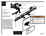
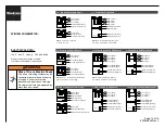
Communication/Data Port Template

Receptacle

Template

Match Receptacle Back Color to Block Color for proper keying.

Impression

NOTE: 

Be sure electrical 

products are in final position 
before making Impressions
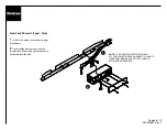
1. 

Install receptacles into

power block.

2. 

Place Communication and

Receptacle Templates.
Steelcase Part No. T500940SR.
(Customer Service)

3. 

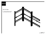
Attach skin to frame. press

against template to make impression.  
Remove skin and template.

OR

RECEPTACLE

FLEX RECEPTACLE

Page 3 of 10

939504633 Rev Y

OR

USB RECEPTACLE

NOTE: This equipment has been tested and 

found to comply with the limits for a Class 

A digital device, pursuant to part 15 of the 

FCC rules.  These limits are designed to 

provide reasonable protection against 

harmful interface when the equipment is 

operated in a commercial environment.  

This equipment generates, uses and can 

radiate radio frequency energy and, if not 

installed and used in accordance with the 

instruction manual, may cause harmful 

interference to radio communications.  

Operation of this equipment in a residential 

area is likely to cause harmful interference 

in which case the user will be required to 

correct the interference at his own expense.

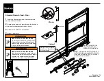
Risk of Fire or Electric Shock

• Receptacle Templates should always be 
used when marking receptacle locations 
on the back of panel skins.

• If the templates are not used, then cut 
opening 1-1/2" x 3-5/8", allowing clearance 
for the mounting screws.

WARNING

Summary of Contents for Answer Modular Power

Page 1: ...tacle Covers New York Power In Feed Floor Pass Thru Power Power Kits Change of Height Harness NOTE Unused modular electrical connector openings are not required to be capped NOTE The electrician can c...

Page 2: ...y conduit around junction glides at the base to the next panel 5a or through power trays and vertical junction 5b or staying Conduit Wire Tie NOTE WIRE TIE THE CONDUIT TO THE VERTICAL JUNCTION SO THE...

Page 3: ...e pursuant to part 15 of the FCC rules These limits are designed to provide reasonable protection against harmful interface when the equipment is operated in a commercial environment This equipment ge...

Page 4: ...e 8 Position skin and attach receptacle covers NOTE When replacing the panel skin make sure that the face plate mounting screws do not make contact with the foil backing of the panel skin Page 4 of 10...

Page 5: ...1 Run the power whip through the frame beam 2 Connect the power whip to the power block 3 Tie up conduit with cable tie NOTE RETAINER CLIPS ARE ATTACHED TO ALL WIDTHS OF POWER KITS 1 2 3 Page 5 of 10...

Page 6: ...tacle opening of the power block 2 Route base power in harness through the backside of the base trim knockout before hard wiring 3 Hardwire the harness to junction box 4 Attach jumper cover WARNING Ri...

Page 7: ...relief bracket to one of the following locations The underside of a utility tray the top or bottom of a beam or the inside face of a junction post 1 Drill a pilot hole for the strain relief bracket mo...

Page 8: ...block down 2 Insert wires from harness into the junction box Make wire connections and assemble junction box NOTE THE QUALIFIED ELECTRICIAN CAN CUT THE POWER IN FEED HARNESS TO LENGTH WIRE END MAKING...

Page 9: ...Pass Thru Power 1 Feed pass thru power harness from panel to panel and connect Page 9 of 10 939504633 Rev Y...

Page 10: ...ternate between P 1 and P 2 to balance circuit loading P 1 P 2 Line 1 Black Line 4 Pink Line 3 Blue Line 2 Red L3 L4 Neutral Gray L1 L2 Neutral White Isolated Ground Gn Yl System Ground Green NEUTRAL...

Reviews: