background image

Assembly Directions
93-9500977  REV  C

Page

3 of 5

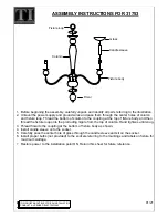
Remove top drawer and adjacent parts 
both sides of case, the wearing of 
gloves is recommended.
a.  Drawer assembly
b.  Drawer track
c.  Rubber bumpers
d.  Lock cam assembly

4.

Turn unit upright and attach front filler to 
case insert with (2) #10 x 1/2” sheet 
metal screws.  Hold filler tight up 
against unit top edge and tighten 
screws.

5.

FRONT FILLER

CASE INSERT

#10 X 1/2” SCREWS

UNIT TOP EDGE

a

b

c

d

Summary of Contents for 41-TSLP

Page 1: ...Steelcase Inc Grand Rapids MI 49501 U S A 1 888 783 3522 Tools Assembly Directions Printed In U S A REV 93 9500977 C Page 1 of 5 Attaching and Assembling a 41 TSLP Typewriter Stand to a 3200 Desk ...

Page 2: ... loosely attach leg to back panel Use 2 1 4 x 9 16 hex head screws Once both screws have been started tighten securely 2 Place leg and back panel assembly on typing shelf and case insert assembly and attach with 2 1 4 x 9 16 hex head screws 3 LEG 1 4 X 9 16 HEX SCREW BACK PANEL LEG BACK PANEL 1 4 X 9 16 HEX SCREW TYPING SHELF CASE INSERT ...

Page 3: ...g of gloves is recommended a Drawer assembly b Drawer track c Rubber bumpers d Lock cam assembly 4 Turn unit upright and attach front filler to case insert with 2 10 x 1 2 sheet metal screws Hold filler tight up against unit top edge and tighten screws 5 FRONT FILLER CASE INSERT 10 X 1 2 SCREWS UNIT TOP EDGE a b c d ...

Page 4: ...age 4 of 5 Slide case insert into drawer opening keep typewriter stand straight to prevent binding and allow proper alignment 6 Align complete unit with desk then secure by adding 6 10 x 3 8 Screws through inside of case insert 3 per side 7 ...

Page 5: ...2 sheet metal screws loosely Do Not Tighten Insert channel clip into bottom of back panel Attach bottom plate to underside of pedestal with 2 10 x 1 2 hex screws threaded into speed nut 8 BACK PANEL PEDESTAL BACK PANEL BOTTOM PLATE 10 X 1 2 HEX SCREWS PEDESTAL CHANNEL CLIP 10 X 1 2 SHEET METAL SCREWS ...

Reviews: