Page 15
◊ ADJUSTING HEIGHT OFFSET
BETWEEN CUTTER HEAD,
CHIPBREAKER AND FEED ROLLERS
The infeed and outfeed rollers pull the workpiece
through the planer. To ensure optimal feeding/cutting
performance, it is important that the height offsets
(conversely the pressures) between the components
are correct.
A
F
B C D e
H
workpiece
How IT worKs:
1. When a workpiece enters the planer, with planer’s depth
of cut properly set, it will clear the depth limiter (
A
). For
workpiece less than 8”, it is possible to bypass the
limiter and receive a deeper cut.
2. The anti-kickback fingers (
B
) then engage the
workpiece to prevent accidental kick-back.
3. As the workpiece moves further into the planer, it will
engage the infeed roller (
C
). The infeed roller will bring
the workpiece towards the chip breaker (
D
) and the
cutter head (
E
).
4. As the cutter head cuts on the workpiece, the woodchips
will be broken down by the chip breaker.
5. The chip breaker and the chip deflector (
F
) then divert
the woodchips towards the dust port for removal.
6. As the workpiece leaves the cutter head, it will engage
the outfeed roller (
G
), which helps pulling the workpiece
away from the planer.
7. The workpiece will also engage the bed roller [
H
] which
helps reducing resistance as the workpiece moves
along the planer table. The height of the bed roller can
be adjusted to accommodate workpiece with various
roughness.
Chip Breaker
Bottom of
Cutting Arc
Cutter
head
Infeed
Roller
Outfeed
Roller
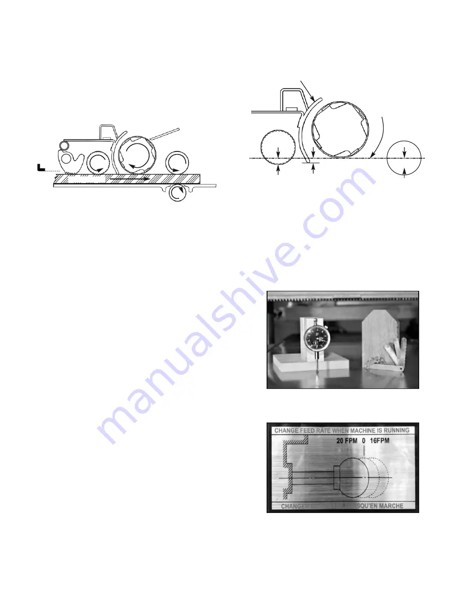
The following diagram shows the height offset between the
cutter head and the other components inside the headstock
of the planer. Adjustments are below the lowest point of the
cutter head and were made at the factory.
The following values are guidelines and might require
further adjustments:
• Infeed roller and chip breaker: 0.004” (0.1 mm)
• Outfeed roller: 0.020” (0.5 mm)
To perform adjustments, you will need a dial indicator
with a stand, or a gauge block with a set of feeler
gauges.
*Diagram not drawn to scale.
1. Turn on the planer, and shift the feed rate control knob
to 0 FPM (Neutral) position. This will allow the feed
rollers to rotate freely.
2.
Turn off planer. Disconnect planer from the power
source.
3. Remove the belt cover so you can rotate the cutter head
with the drive belt.
Example, to check the outfeed roller’s offset:
G
Summary of Contents for 35-215S3
Page 19: ...Page 19 PArTs LIsT 35 215s3...
Page 20: ...Page 20 35 215s3...
Page 21: ...Page 21 35 215s3...
Page 22: ...Page 22 35 215s3...
Page 23: ...Page 23 35 215s3...
Page 24: ...Page 24 35 215s3...


