2. To replace the solenoid coil, disconnect
lead wire terminal screws (139S), lock
washers (139W) and lead wires (139).
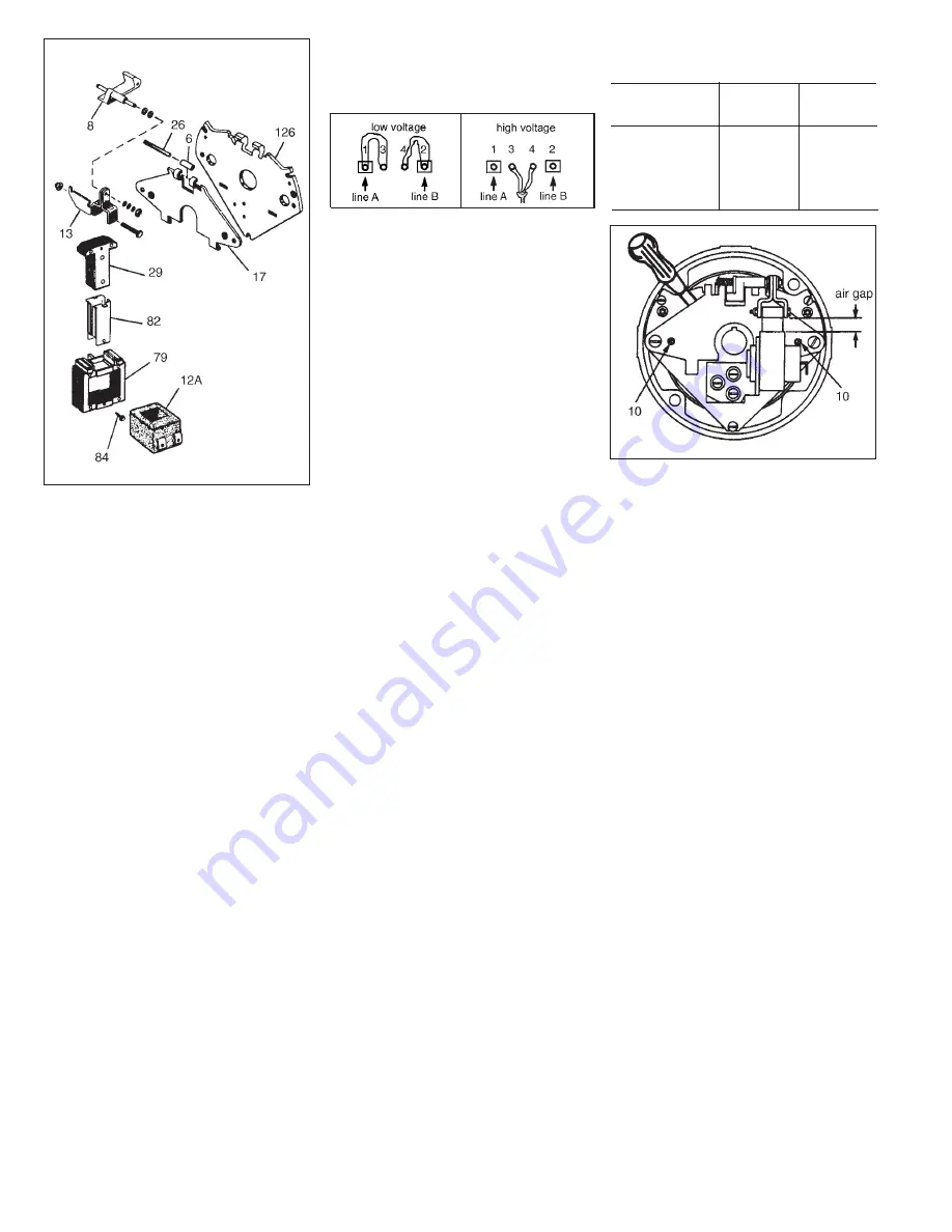
3. Insert a screwdriver between support
plate (126) and top of lever arm (17).
With screwdriver wedge apart; remove
bearing pin (26) and solenoid lever (8)
with solenoid link (13) and plunger
(29). It is not necessary to separate
the solenoid lever, solenoid link and
plunger.
4. Remove plunger guide screw(s) (84).
Remove both plunger guides (82) by
prying up on the flanges. Discard
plunger guides.
5. Slide coil (12A) sideways from
solenoid frame (79). If necessary, tap
coil lightly with soft hammer. If coil had
burned out, be sure to remove all
foreign material from the solenoid
plunger (29) and solenoid frame (79).
6. Install new coil (12A) into solenoid
frame with same relative position as
old coil. Assemble new plunger guides
(82) and plunger guide screws(s) (84).
7. Low Voltage:
Jumper leadwire 3 to terminal 1
Jumper leadwire 4 to terminal 2
Incoming power to terminals 1 & 2
8. High Voltage:
Jumper leadwires 3 & 4 together
Incoming power to terminals 1 & 2
9. Be sure to check the following when
installing lead wires:
1) Must not be tight or pinched.
2)
Must not make contact with
friction disc.
3)
Must not be trapped between
solenoid plunger and frame.
10. Manually lift solenoid plunger to
maximum travel. Depress and allow
solenoid plunger to snap out several
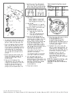
times. Measure solenoid air gap
between mating surfaces of solenoid
frame and solenoid plunger. (On
vertically mounted brakes, it will be
necessary to push solenoid plunger
into solenoid frame to the point where
spring pressure is felt, before
measuring solenoid air gap.)
If solenoid air gap exceeds 11/16”,
adjustment is necessary.
The solenoid air gap measurements
are shown in Table in next column.
11. The solenoid air gap may be
decreased by turning both wear
adjustment screws (10) equal amounts
clockwise, approximately 1/8 turn, until
appropriate solenoid gap is attained.
To increase gap, turn screws
counterclockwise.
12. Reconnect coil leads.
13. Orient housing so that manual release
knob is approximately 20°
counterclockwise from vertical
centerline. Slide housing over
endplate register and rotate clockwise
to align bolt holes. Replace hardware
in reverse order of Step 1.
14.
Caution 1!
Do not run motor with
brake in manual release position. It is
intended only for emergency manual
movement of the driven load, not as a
substitute for full electrical release.
Caution 2!
Class H coils with
terminals. Do not bend lead wire
crimp connection as this causes
fatigue in the metal which may break
under vibration.
NOTE: For complete instructions,
with
troubleshooting
, request sheet
applicable to the series of brake that
you have.
Nominal Static
Torque (lb-ft)
65,000
Series
65,300
Series
1.5 and 3
13/32
13/32
6
13/32
13/32
10
1/2
1/2
15
9/16
9/16
Table: Solenoid Air Gap Measurement
(inches)
Copyright
©
1999-2006 by Rexnord Industries, LLC
Rexnord Industries, LLC, Stearns Division, 5150 S. International Dr., Cudahy, Wisconsin 53110, (414) 272-1100 Fax (414) 277-4364


