


Note 2:
Check face of motor, machine or
foot mounting bracket to which brake is to
be mounted to be sure NEMA dimensions
of 0.004” T.I.R. on concentricity and face
run out are met. Shaft run out is to be
0.002” T.I.R. Maximum shaft end float is
0.020”. On foot mounted brakes, dowels are
recommended for bracket.
2. Use a key (not supplied) tight fitting and
full axial length of hub (16). Slide hub
on shaft positioning inboard face of hub
about 3/16” from mounting face or at
5/16” for 57,500 Series. See Figure 3.
Securely tighten both hub set screws
(16S) with torque of 78 in-lbs on 1/4”
and 156 in-lbs on 5/16”. Recommended
practice is to drill a set screw dimple into
shaft, especially on vertical installation.
Figure 3
3. Attach brake to mounting face by sliding
brake friction disc(s) (4) over hub,
engaging without force. Brake endplate
(2) face is to be tight against mounting
face.
Note 3:
If motor or assembly is to be ceiling
or horizontally wall mounted, orient brake so
that plunger will be above solenoid frame at
final installation.
4. Install 3/8” – 16 cap screws (not supplied)
or 1/2” size for 57,500 Series to attach
endplate to mounting surface. Tighten
to manufacturer’s recommended torque.
Continue with Step D.
B. Method of installing 55,000 and
55,400 Series with waterproof, dust-tight
enclosure:
1. Remove screws (142S) and support plate
assembly (142).
2. Remove stationary disc(s) (3) and friction
disc(s) (4).
Note:
Vertically mounted multi-disc brakes
have special pins which guide vertical
mounting springs. Observe color coded
sequence of springs from reinstallation.
See Notes 1, 2 and 3 in
Method I-A of
Installing Brakes with Standard Enclosure
.
3. Attach endplate (2) to mounting face
and tighten 3/8” – 16 cap screws
(not supplied) to manufacturer’s
recommended torque.
4. Use a key (not supplied) tight fitting and
full axial length of hub (16). Slide hub on
shaft positioning square inboard face of
hub 1/32” to 1/16” from unfinished cast
surface of endplate (2). See
Installation
Procedure,
A, Step 2 for set screw
tightening.
5. Reassemble friction disc(s) (4) and
stationary disc(s) in the same order,
being sure all slide freely without binding.
If vertical mounting springs are used, be
sure to reassemble in original sequence
or refer to Sheet 301.4.
6. Mount support plate assembly (142)
and torque screws (142S) evenly to 43
in-lbs. Be sure plunger is above frame on
horizontal brakes. Continue with Step D.
C. Method of installing 55,200 Series:
1. Do not disassemble brake.
2. Bolt foot mounting bracket to a suitable
base.
3. For in-line coupling, follow coupling
manufacturer’s suggestions on alignment.
4. If installing pulley or sprocket on brake
shaft, do not use excessive force during
installation. Maximum overhung load at
center of keyway length is 150 lbs.
5. After alignment, dowels are suggested to
maintain alignment.
6. Remove housing (7). Continue with
Step D.
D. For all sizes
1. Refer to solenoid air gap, Table 2 in
Section IV-A. Follow Steps 1 and 2
for checking and air gap adjustment, if
necessary.
2. See Section II,
Electrical Connection of
the Brake,
for coil connection.
3. Replace housing. On 55,300; 55,500 and
57,500 Series Brake, tighten housing
nut (15) 3/4 to 1 turn (8 in-lb) beyond
contacting the housing surface. On
55,000 and 55,400 Series standard
enclosure brake, tighten housing nut 1/4
turn (30 in-lb) beyond contacting housing.
On 55,000 and 55,400 Series DTWP
enclosure brake, housing nut gaskets are
provided. Tighten housing nut 1/2 to 3/4
turn (20 in-lb) beyond contacting gasket
on housing.
Note:
If brake is
upside down
for later
ceiling mount, turn brake upright before
installing housing.
II. Electrical Connection of Brake
CAUTION: Inverter Motor and Special
Control Systems.
This brake contains
either a single phase AC coil or DC coil
that requires instantaneous power within ±
10% of rating at the coil. A separate power
source is required when this brake is used
in conjunction with a motor or control system
that limits voltage or current input (i.e.
inverter motors) or causes a ramping of the
power supply.
Note 1:
Brake coil connections described
here cover common motor connections. For
nonstandard motor or control connections
contact respective supplier or Stearns
Division.
Note 2:
On brakes with space heater,
connect to appropriate power source. Heater
is to be energized continuously, even during
storage, if rust may occur.
Note 3:
Be sure lead wires to coil are not
tight or pinched, and that leads will not be
rubbed by friction disc, trapped between
solenoid plunger and frame, caught between
lever arm and endplate, or by linkage.
A. AC coils – single and dual voltage
1. All Stearns AC coils are single-phase.
Connect single voltage coils to any two
wires of single or three-phase power
source, or, for operation with motor
control, to any two motor leads of proper
voltage.
Method of connecting dual voltage coil
for use on high or low voltage is shown
in Figure 4. Observe the lead numbering
sequence for proper connection as shown
in next column.
2. To use a 230 volt coil (or a dual voltage
coil connected for 230 volts) with a
230/460 dual voltage three-phase motor,
the brake leads are connected across
two motor terminals as shown, or other
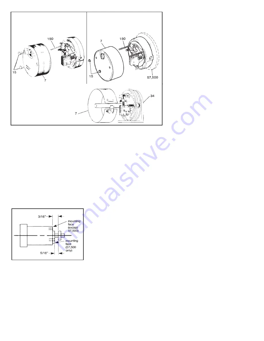
55,000 and 55,400 Series
Remove housing nuts (15) by unscrewing
from housing studs (150), remove
housing (7) by pulling back.
55,500; 55,300 and 57,500 Series
Remove housing nuts (15) by unscrewing
from housing studs (150), remove
housing (7) by pulling back.
55,200 Series
Remove wraparound sheet metal
housing (7) by turning wing-nut on
latch counterclockwise until latch
releases.
Figure 2