background image

04/18

Pub. No. 231-B

- 2 -

Electrical Installation Instructions

Models: SMP-12 and SMP-15

The Steam Generator is installed in an upright position.
The proper sized 90°C copper wire and circuit breaker 

have been used.
The circuit breaker is NOT a GFI (Ground Fault 

Interrupter) type.
The Steam Generator is properly grounded.
The circuit breaker or disconnect switch is on.
Water supply is open to the Steam Generator.

Checklist

Before starting, insure that the conditions of the following checklist have been met:

The proper size Steam Generator has been selected by 

using the sizing page in the “Full Line Brochure,” “Pricing 

Guide,” or “The Generator Sizing Guide” in the Residen

-

tial Systems/Steambath Product Information section of 

the Steamist website - www.steamist.com.

CAUTION:

 An improperly sized Steam Generator will 

NOT produce the amount of steam necessary to reach 

selected temperature.
The proper voltage Steam Generator has been selected 

(i.e., 208V or 240V). A 208V Generator operating on 

240V will damage the heating element, and a 240V 

Generator operating on 208V will result in a 25% 

loss of power.

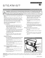
Water

Level

Probe

Optional Auto

Drain Connection

Test button

Troubleshooting LED’s

Modular Jacks

(Plug control cable 

into any connector)

PC Board

Summary of Contents for SMP-12

Page 1: ...ll be installed If receptacle is desired mount the box for the receptacle near the location of the Steam Generator NOTE The plug and receptacle require a rating of no less than 250V and proper amperage Refer to chart on page 4 for amperage rating After the walls are complete the Steam Generator and Control can be wired 3 Steam Generator Electrical Installation WARNING All power to the Steam Genera...

Page 2: ...e Steam Generator has been selected by using the sizing page in the Full Line Brochure Pricing Guide or The Generator Sizing Guide in the Residen tial Systems Steambath Product Information section of the Steamist website www steamist com CAUTION An improperly sized Steam Generator will NOT produce the amount of steam necessary to reach selected temperature The proper voltage Steam Generator has be...

Page 3: ...red IMPORTANT Run the Control Cable through a conduit Remove protective cap when making the final connection to Control TSX Auxilary Outside Control Figure 4 Typical Installation Models SMP 12 and SMP 15 STOP 2 1 SHOWER STEAM SHOWER STEAM 1 1 2 2 9 31 IM Inside Installation Control should be mounted four feet from the floor Select a location convenient to the bather but not in a direct line of Sho...

Page 4: ...n Installation shall be in accordance with appli cable electrical codes East Coast Office 25 E Union Ave East Rutherford NJ 07073 Tel 800 577 6478 Fax 201 933 0746 West Coast Office Tel 800 355 6478 Fax 661 940 1617 DRAIN DS13 STEAMIST INC ASSEMBLY NO 007 3427 0 5A 250VAC J11 F3 J9 J10 J12 SW2 F1 F2 DS9 RH1_L2 RH2_L2 RH3_L2 RH1_L1 RH2_L1 RH3_L1 DS5 DS6 DS4 DS7 DS8 S1 TEST 0 8A 250VAC H2O LO SEN H2...

Reviews: