background image

User & Workshop Manual for the Lightning Upholstery

20

10.0       INSTRUCTIONS FOR ATTACHING THE WORK ‘N’ PLAY TRAY

                 The below instructions are for attaching the Work ‘n’ Play tray to the

                 Lightning Pushchair.

                 CAUTION: THE TRAYS HAVE BEEN RATED TO HOLD UP TO 6.8kgs

                 15lbs OF WEIGHT.  DO NOT OVERLOAD.

                 WARNING: REMOVE THE TRAY WHEN TRANSPORTING USER IN A

                 MOVING VEHICLE.

    10.1  Contents

                •  Pl

astic Tray

                •  2 Locking Pins

    10.2     Attaching And Removing The Tray

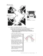
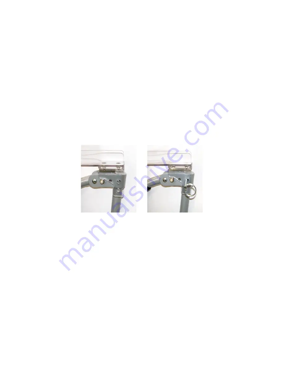
                10.2.1   Place the tray on top of the armrest handles as shown on Fig. 1.

                10.2.2   Insert a locking pin to both sides as shown on Fig. 2.

                10.2.3   For removal, ensure that the tray is free from objects and release

                             the tray by removing both locking pins.

11.0 

CLEANING


    11.1   Frame

                11.1.1   To clean the frame, wipe with a damp cloth and dry thoroughly.
                11.1.2   For more stubborn stains wipe with a damp cloth and warm water.

                             in which a little mild soap has been dissolved. Dry thoroughly.
                11.1.3   Never use furniture polish or any spirit to clean the frame.


    11.2   Upholstery

                11.2.1   Remove the seat and back upholstery from the Pushchair.  
                11.2.2   Remove the harness and support boards from the upholstery. 
                11.2.3   Machine wash in cold water on delicate cycle.
                11.2.4   Dry cover thoroughly before re-assembly. Do not tumble dry.


    11.3   H-Harness

                11.3.1   Remove harness from Pushchair.
                11.3.2   Wipe with a damp cloth and dry thoroughly. Do not tumble dry.
                11.3.3   Do Not immerse in water or wash in a machine

Fig. 1

Fig. 2

Summary of Contents for LIGHTNING PUSHCHAIR

Page 1: ...LIGHTNING PUSHCHAIR USER WORKSHOP MANUAL FORTHE...

Page 2: ...Harness 13 7 7 Brake System 14 8 0 Installing Accessories 15 8 1 Headrest Extension 15 8 2 Canopy 15 8 3 Padded Headrest 15 8 4 Heel Loop and Ankle Cuffs 16 8 5 Padded Harness Covers 16 8 6 Trunk Sup...

Page 3: ...Accessories or parcels placed in or on the Pushchair may cause it to become unstable To avoid burns never put hot liquids in the working tray Care must be taken when folding and unfolding the product...

Page 4: ...SEAT DEPTH ADJUSTABLE 1 to 12 15 with optional Kit FOOTREST EXTENSION From 1 to 12 in 1 increments standard LT14 LT14SE MODEL HEAVY DUTY UPHOLSTERY includes moldable stays FRONT RIGGING SWING AWAY FL...

Page 5: ...members because of its superb strength to weight properties WHEEL LOCKS Operates both sides with single actuation FOLDING ACTUATOR PUSHCHAIR FEATURES LT16 LT16SE MODEL HEAVY DUTY UPHOLSTERY includes...

Page 6: ...1 RC LT14 RC LT16 RC SINGLE FLAP Adjustable Lateral Trunk Support Red Item Blue Item LT11 RSF LT11 BSF LT14 RSF LT14 BSF LT16 RSF LT16 BSF DOUBLE FLAP Adjustable Lateral Trunk Support w Double Pads Re...

Page 7: ...CHAIR without riggings 25 lbs 27 lbs 28 lbs WEIGHT CAPACITY 75 lbs 100 lbs 150 lbs FRAME COLOR CHOICES SILVER SILVER SILVER UPHOLSTERY COLOR CHOICES NAVY BLUE RED GLOW NAVY BLUE RED GLOW NAVY BLUE RED...

Page 8: ...the health insurance companies FRG Rehab buggies are indicated for the transport of patients with severe disabilities mainly children and adolescents who are unable to walk and or to move independentl...

Page 9: ...the folding locking mechanism with foot Hold in the down position and push the back forward toward the seat Place the left side of the Pushchair on the floor On the right side maneuver the Velcro stra...

Page 10: ...Adjustment To adjust back angle you must remove back upholstery Remove the top Velcro strap Remove the lower Velcro strap Remove both left and right side backrest tubes The diagram to the right will s...

Page 11: ...nch remove the adjustment nut on both sides Move to the desired angle position and fasten the nuts with the 10mm wrench LT16 Adjustment 16 18 406 4 457 2mm LT14 Adjustment 12 14 304 8 355 6mm LT11 Adj...

Page 12: ...e Adjustments LT16 1 17 25 4 431 8mm LT14 1 17 25 4 431 8mm LT11 1 12 25 4 304 8mm Remove the locking pin Move the footrest to the desired height location And replace the locking pin Using a 10mm wren...

Page 13: ...he Crotch Strap With the button facing up guide the strap through the mid section of the holder Then guide the strap under and over the crotch strap ring Finally adjust the strap to the desired length...

Page 14: ...ghten Locking and unlocking the safety harness To lock insert both left and right side harness pins into push button slots To unlock press the red push button and gently pull back To engage brake With...

Page 15: ...the canopy into the backrest accessory tubes or if headrest extension is in place insert into headrest extension tube The headrest extension is required for installation of the headrest pad From the h...

Page 16: ...around the harness straps and fasten one side of the Velcro to the other 8 5 Padded Harness Covers Guide the screw from the ankle cuff through the top of the footrest On the bottom of the footrest pla...

Page 17: ...Pushchair and fasten it around the back set using the Velcro straps On both sides wrap the bottom support flap Velcro straps around the lower armrest tube Using the loose strap guide it through both t...

Page 18: ...the headrest extension must be fitted 9 1 3 Remove the following if fitted Work N Play Tray Rain hood Shopping Basket or Sun Canopy 9 2 Attach The Set Of 4 Tie Down Kit Brackets This Instruction is s...

Page 19: ...e front of the Lightning facing towards the front of the vehicle in the direction of travel Put the Brakes on Attach the front restraints to the floor track and the front Tie Down Brackets making sure...

Page 20: ...ree from objects and release the tray by removing both locking pins 11 0 CLEANING 11 1 Frame 11 1 1 To clean the frame wipe with a damp cloth and dry thoroughly 11 1 2 For more stubborn stains wipe wi...

Page 21: ...ekly 12 1 4 Clean frame when necessary we suggest at least once a week 12 2 Six Months Maintenance Someone who is a competent tradesman or repairer should only carry out this work If a major fault is...

Page 22: ...e with a new Nyloc nut Always use recommended components and parts available from Tendercare Ltd Do not modify or repair frame 13 1 Front Wheel Assembly Insert the shoulder bolt from outside the wheel...

Page 23: ...10mm wrench Insert the shoulder bolt from the outer part of the wheel Through the wheel and To the inside wheel mount Place the washer and nut on the inside of the wheel caster Then tighten with neces...

Page 24: ...s Slip the upholstery out of the tubes For reassembly follow steps in reverse order To replace the seat upholstery Press both depth release buttons Slide seat tubes out of tube receiver Unscrew both b...

Page 25: ...repair or replace free of charge any parts or part found to be defective due to manufacturer within a period of 12 months from the date of delivery 14 2 The above will not repair or replace free of ch...

Page 26: ...P O Box 458 103 John Kelly Drive Burnet TX 78611 phone 1 800 965 9229 fax 1 800 806 1225 e mail info stealthproducts com www stealthproducts com...

Reviews: