

D2572-01-06
5~USER CONFIGURATION.
Read the Important safety requirements
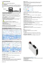
PC CONFIGURATION
During configuration the equipment takes its power from the USB port, therefore no
power connection is required. The equipment can be configured whilst powered but the
computer used must be isolated from the supply earth to avoid grounded earth loop
effects.
Device
USBSPEEDLINK software
www.status.co.uk
USB CABLE
COMPUTER
Configuration steps using USBSpeedLink
Download, install and run USBSpeedLink
Up to 8 configurations can be stored, the configuration chosen is set using a
DIP switch.
Set the switch on the SEM1720 to the required position (default position 1). The
switch is located behind the front panel. Repower the device after changing the
DIP switch position.
Do not remove front panel while the device is powered!
Connect device to PC using an A to mini B USB lead
Upload device set-up into the configuration software, “Basic” and “Advanced”
options are available for configuring the device.
Basic mode should be suitable for most applications.
An enhanced set of programming options are available in the Advanced
configuration mode.
Adjust settings as required
Send new configuration to the device
USBSpeedLink software configuration screen for SEM1720
Note: When the device is correctly connected, the “Send” and “Receive” menu buttons
will turn black and the “Read Data” button will become visible.
Basic configuration
screen shown below.
Advanced configuration
screen shown below
The following covers the Advanced mode, but descriptions apply to Basic mode as well.
CH In/Input
(Ch1 and Ch2)
Select
:
RTD, TC or Slide-wire. RTD and TC will give a dropdown option for type.
CH In/Input
(Ch1 and Ch2)
Select
:
High or Low condition for On Error Fail (burnout).
CH In/Input
Pre-set (Ch1 and Ch2)
This will open a box to enter a value for the input (°C, %) that the device will take as its
input condition. The actual input will be ignored while this input pre-set is selected. The
device will respond accordingly to the pre-set input value on its output.
Profile
In (A and B)
Select the input source for the Profile, normally CH1 or CH2 input, but can use the
dropdown tool to select from a range of maths comparisons such as Average.
Profile
Seg/Segments (A and B)
The number of segments
Up to 22 user-segments can be used to create a user-curve or non-linear relationship
table, for example add corrections or calibration points to a probe with known errors.
This tool can also be used to enter the °C units to °F units if required.
Segments can be used if required to control out of limit conditions or create banded
temperature zones.
Profile
Units Out (A and B)
Normally
°C but can be any relevant unit such as °F (see above
Seg/Segments)
CH Out/Output
Source (Ch1 and Ch2)
Select the Profile source for the Output, normally Profile A or Profile B, but can use the
dropdown tool to select from a range of maths comparisons such as Average.
CH Out/Output
Range (Ch1 and Ch2)
Set the engineering range, normally °C to be scaled to the output.
CH Out/Output
Signal
(Ch1 and Ch2)
Select mA or V and the output range to be scaled to the engineering range. This can be
any value within the physical capability of the device.
For a voltage output, the output load value, if known, can also be entered.
CH Out/Output
Damping (Ch1 and Ch2)
A value to slow the rate of change on the output can be added for a rising and a falling
signal.
CH Out/Output
Fixed Output (Ch1 and Ch2)
The output can be fixed to a known value. This can be useful for diagnostics on a
system
CH
Out/Output
Tag (Ch1 and Ch2)
A free type field for information to be stored onto the SEM1720
Menu Options
The configuration can be saved to PC file for back-up and re-use as required.
The USBSpeedLink software will allow live readings to be taken from the device
showing input and output conditions.
For diagnostic use, the device can save live readings to a text file on the PC.
USBSpeedLink configuration software is available online at
This guide is also available online at
Status Instruments Ltd, Status Business Park, Gannaway Lane, Tewkesbury, Gloucestershire, UK, GL20 8FD,
Web Page: www.status.co.uk,
Email: [email protected]
Technical Support: [email protected]
Tel: +44 (0) 1684 296818, Fax: +44 (0) 1684 293746


