Quick-Start Guide
To view manuals, FAQs, videos, drivers, downloads, technical drawings, and more, visit www.startech.com/support.
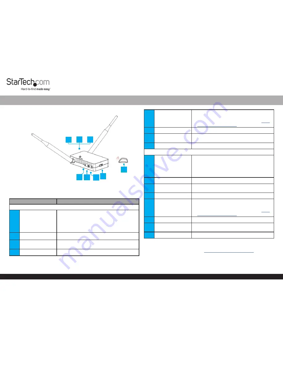
Product Diagram (ST121WHDLR)
Note:
The above image represents both
Transmitter
and
Receiver
. The ports are
located in the same position on both the
Transmitter
and
Receiver
.
Port/Button/LED/Part
Function
Transmitter
1
Pairing/Channel
Button
•
Pairing:
Used to pair devices to the
Wireless
Transmitter
.
Note:
Press and hold for 5 seconds.
•
Channel:
For better transmission, use the
Channel
Button
to use another channel.
2
Network LED
• Solid red indicates that the network is connected.
3
Video LED
• Solid blue indicates that the
Display Device
is
connected.
4
IR OUT Port
• Connect an
IR Blaster
to transmit an IR signal.
HDMI over Wireless Extender |1080p | 200 m
4
5
USB Port
• Used for firmware updates.
Note:
For future firmware updates refer to the
firmware section on the Product Support tab
www.
startech.com/ST121WHDLR
.
6
DC 5V Port
• Powers the
Wireless Extender
.
7
HDMI IN Port
• Connects the
Video Source Device
to the
Wireless Extender
.
8
IR Blaster
• Used to transmit an infrared signal.
Receiver
1
Pairing/Channel
Button
•
Pairing:
Used to pair devices to the Wireless
Receiver.
Note:
Press and hold for 5 seconds.
•
Channel:
For better transmission, use the
Channel
Button
to use another channel.
2
Network LED
• Solid red indicates that the network is connected.
3
Video LED
• Solid blue indicates that the
Display Device
is
connected.
4
IR IN Port
• Connect an
IR Receiver
to receive an IR signal.
5
USB Port
• Used for firmware updates
Note:
For future firmware updates refer to the
firmware section on the Product Support tab
www.
startech.com/ST121WHDLR
.
6
DC 5V Port
• Powers the
Wireless Extender
.
7
HDMI OUT Port
• Connects the
Display Device
to the
Wireless
Extender
.
8
IR Receiver
• Used to receive an infrared signal.
Requirements
For the latest requirements, please visit
www.startech.com/ST121WHDLR
.
5
7
6
1
2
3
8
1


