background image

Instruction Manual

5

Installation

      WARNING!

 PCI Express cards, like all computer equipment, can be severely  

      damaged by static electricity. Be sure that you are properly grounded before 

      opening your computer case or touching your card. StarTech.com 

recommends that you wear an anti-static strap when installing any computer 

component. If an anti-static strap is unavailable, discharge yourself of any static 

electricity build-up by touching a large grounded metal surface (such as the computer 

case) for several seconds. Also be careful to handle the card by its edges and not the 

gold connectors.
1.  Turn OFF the computer power before installation.
2.  Remove the chassis cover from your computer.
3.  Locate an unused PCI Express slot and remove the corresponding slot cover from 

rear panel of the computer chassis. Retain the screw (if applicable) used to hold the 

slot cover in place.

4.  Align the PCI Express card with the unused PCI Express expansion slot. Applying 

pressure evenly across the top edge of the expansion card, firmly but gently insert the 

card into the slot, ensuring that the card is properly aligned with the rear panel slot.

5.  Secure the card to the motherboard and rear chassis using the screw removed in 

step 3 (if necessary). Secure the additional serial port provided by the daughter 

board (smaller circuit board to an adjacent rear bracket.

6.  Replace the chassis cover (removed in step 2).
7.  Connect the 4-port breakout (octopus) cables to the ports provided by PEX8S950LP.
8.  Power on the computer. Once the computer has been rebooted, the operating 

system will detect that the PCI Express card has been installed and request driver 

installation, detailed in the next section.

Software Installation

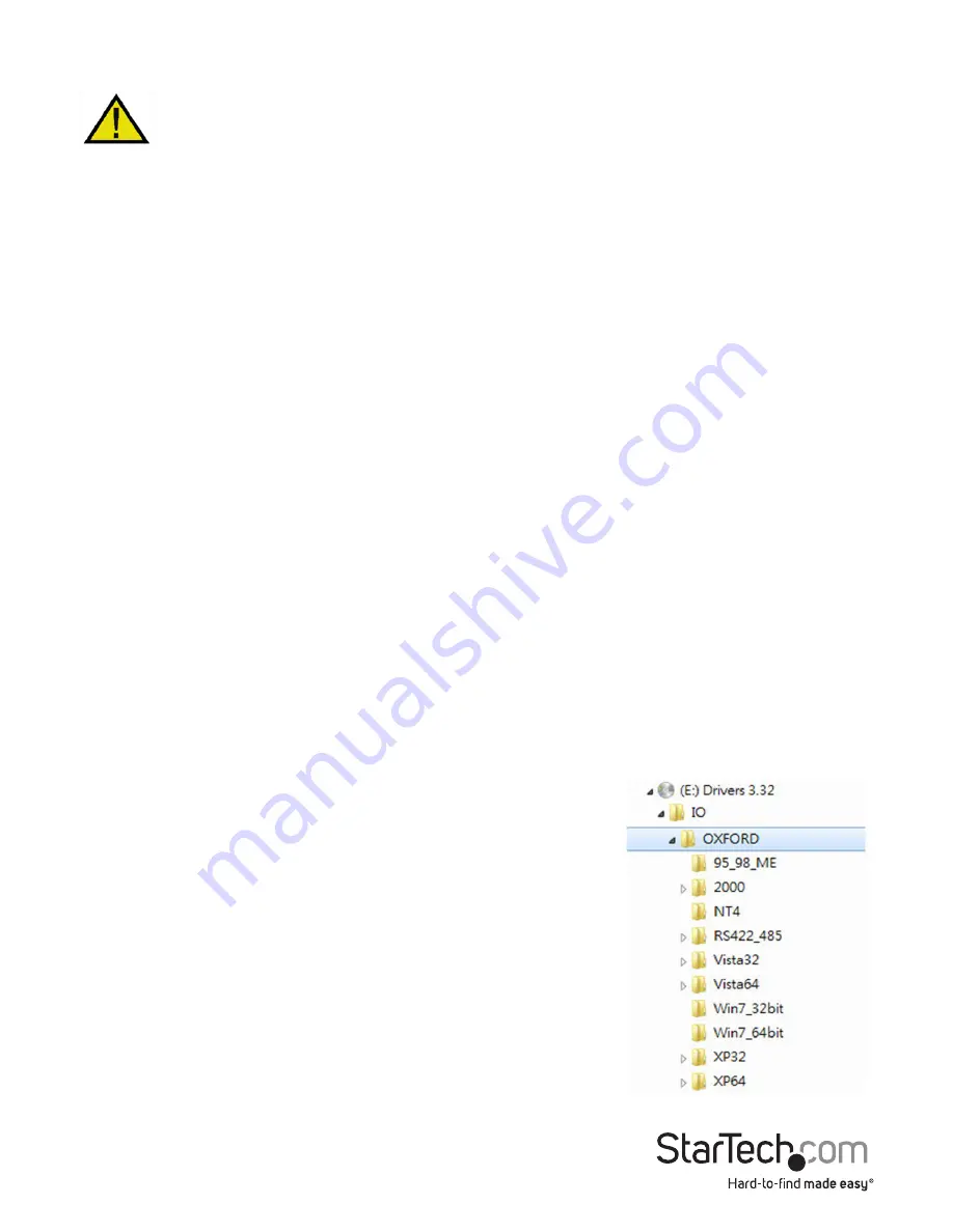
To install the necessary drivers for use with PEX8S950LP,  

simply insert the Driver CD into the CD/DVD-ROM drive 

on the host computer, and follow the prompts provided  

by the operating system. When asked to specify the  

location of the files, please select Browse and guide the  

Hardware Wizard to the exact folder location where the  

driver is located. (E:\IO\OXFORD\NT4 folder where E: is  

the CD/DVD-ROM drive).
Allowing Windows to search for the file may result in the 

incorrect file being installed, as the Driver CD contains  

several versions of the necessary software. As such, please  

pay particular attention when designating the folder from  

which to install the driver files.

Summary of Contents for PEX8S950LP

Page 1: ...leitung de startech com FR Guide de l utilisateur fr startech com ES Gu a del usuario es startech com IT Guida per l uso it startech com NL Gebruiksaanwijzing nl startech com PT Guia do usu rio pt sta...

Page 2: ...ceiving antenna Increase the separation between the equipment and receiver Connect the equipment into an outlet on a circuit different from that to which the receiver is connected Consult the dealer o...

Page 3: ...troduction 1 Packaging Contents 1 System Requirements 1 Hardware Guide 2 Installation 5 Software Installation 5 Configuration 6 Specifications 7 Connector Pin Assignments 7 General Specifications 8 Te...

Page 4: ...total of 8 ports The perfect choice for adding several additional ports when space is at a premium the serial adapter card is designed to fit in small micro form factor computer cases Plus this versat...

Page 5: ...ts will be swapped as follows where S designates the port number S1 S5 S2 S6 S3 S7 S4 S8 S5 S8 DB44 Pin Connector to 4 port breakout cable Ports 5 8 JP 3 Power over Serial Connectors Enable Disable Po...

Page 6: ...P position it will output the DC power over pin 9 if set to the D position pin 9 will be connected to the normal RI signal based on the RS232 standard JP4 Power Source Selector Used to select DC power...

Page 7: ...ions Lo factory default The clock is set to 1 8432MHz with a maximum baud rate of 115 2Kbps Hi The clock is set to 14 7456MHz with a maximum baud rate of 921 6Kbps Please see the section entitled Conf...

Page 8: ...is properly aligned with the rear panel slot 5 Secure the card to the motherboard and rear chassis using the screw removed in step 3 if necessary Secure the additional serial port provided by the dau...

Page 9: ...ent window 1 In the left pane click on Device Manager Here you should see two listings for PCI Communications Port as illustrated below 2 Right click on the first listing and select properties to laun...

Page 10: ...3 Port 4 42 DCD1 39 DCD2 35 DCD3 31 DCD4 14 RXD1 10 RXD2 6 RXD3 2 RXD4 13 TXD1 9 TXD2 5 TXD3 1 TXD4 29 DTR1 25 DTR2 21 DTR3 17 DTR4 44 GND 41 GND 37 GND 33 GND 30 DSR1 26 DSR2 22 DSR3 18 DSR4 15 RTS1...

Page 11: ...to 921 6Kbps Data Bits 5 6 7 8 9 Stop Bits 1 1 5 2 I O address IRQ Plug and Play various Parity None Even Odd 1 0 Flow Control RTS CTS XON XOFF Power Requirement 3 3V 800mA Operating Temperature 0 to...

Page 12: ...returned for repair or replacement with equivalent products at our discretion The warranty covers parts and labor costs only StarTech com does not warrant its products from defects or damages arising...

Page 13: ...ts and we quickly deliver them wherever they need to go Just talk to one of our tech advisors or visit our website You ll be connected to the products you need in no time Visit www startech com for co...

Reviews: