background image

Instruction Manual

5

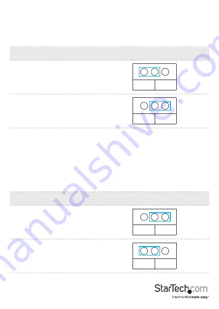
JP3 and JP2 - Serial port power

These two jumpers are used to provide external power to the two breakout cables or 

the 16 serial ports. JP3 enables or disables power over ports 1 to 8, and JP2 enables or 

disables power over ports 9 to 16. When enabled, the card connects DC power to pin 9 

of the DB9 port(s).

JP1: Power selector

Setting

No power is supplied to pin nine on the serial 

ports

Power is supplied to pin nine on the serial ports 

and the power source is determined by what is 

selected at JP1

DIS

ENA

DIS

ENA

JP4 – UART power selector

Leave at the default setting (3.3V).

JP5 - Mode setting

This is for factory test purposes only. The jumper must be fixed at SB.

JP6 - PME setting

This jumper enables or disables wake from sleep.

JP1: Power selector

Setting

PME is disabled

PME is enabled

ENA

DIS

ENA

DIS

(default)

Summary of Contents for PEX16S550LP

Page 1: ... www StarTech com PEX16S550LP FR Guide de l utilisateur fr startech com DE Bedienungsanleitung de startech com ES Guía del usuario es startech com NL Gebruiksaanwijzing nl startech com PT Guia do usuário pt startech com IT Guida per l uso it startech com PEX16S550LP 16 Port Serial Card actual product may vary from photos ...

Page 2: ...adio TV technician for help This device complies with part 15 of the FCC Rules Operation is subject to the following two conditions 1 This device may not cause harmful interference and 2 this device must accept any interference received including interference that may cause undesired operation Changes or modifications not expressly approved by StarTech com could void the user s authority to operat...

Page 3: ...FCC Rules Operation is subject to the following two conditions 1 This device may not cause harmful interference and 2 this device must accept any interference received including interference that may cause undesired operation Changes or modifications not expressly approved by StarTech com could void the user s authority to operate the equipment Industry Canada Statement This Class B digital appara...

Page 4: ... contents 3 Requirements 3 About the jumpers 4 JP1 Power selector 4 JP3 and JP2 Serial port power 5 JP4 UART power selector 5 JP5 Mode setting 5 JP6 PME setting 5 Hardware installation 6 Install the low profile bracket 6 Install the PCIe Card 6 Software installation 7 Install the driver Windows 7 Technical support 8 Warranty information 8 ...

Page 5: ...gram Top view Front view Bracket full profile pictured PCI Express x1 connector JP4 VART power JP6 PME JP1 AUX power source SATA power connector JP5 Mode JP2 PWR 9 16 JP3 PWR 1 8 Screw locks Screw locks VHDC1 68 port 2 VHDC1 68 port 1 ...

Page 6: ...mall form factor computer through a PCI Express expansion slot It s a convenient solution for connecting modern or legacy serial devices to your computer with support for data transfer rates up to 921 6Kbps It includes two 8 port breakout cables so you can connect up to 16 serial devices to this single card even in low profile computer systems ...

Page 7: ... a PCI Express x1 slot A CD ROM DVD ROM or other compatible optical drive for driver CD installation RS232 serial cables DB9 Any of the following operating systems Windows 10 Windows 8 1 Windows 8 Windows 7 Windows Server 2012 Linux 2 4 x and later tested up to 4 04 Requirements are subject to change For the latest requirements please visit www StarTech com PEX16S550LP ...

Page 8: ...per s position JP1 Power selector Setting Internal 5V Power source is 5VDC from the motherboard s PCI Express slot Internal 12V Power source is 12VDC from the motherboard s PCI Express slot Internal 12V Power source is 12VDC from the motherboard s PCI Express slot Internal 5V Power source is 5VDC from the motherboard s PCI Express slot 15V I12V X12V X5 15V I12V X12V X5 15V I12V X12V X5 15V I12V X1...

Page 9: ...e DB9 port s JP1 Power selector Setting No power is supplied to pin nine on the serial ports Power is supplied to pin nine on the serial ports and the power source is determined by what is selected at JP1 DIS ENA DIS ENA JP4 UART power selector Leave at the default setting 3 3V JP5 Mode setting This is for factory test purposes only The jumper must be fixed at SB JP6 PME setting This jumper enable...

Page 10: ...ny built up static electricity by touching a large grounded metal surface for several seconds 1 Turn off your computer and any devices or peripherals that are connected to it such as printers or external storage devices 2 Unplug the power cable from the back of your computer 3 Disconnect any peripheral devices that are connected to your computer 4 Remove the cover from your computer case Consult t...

Page 11: ...Manager 3 Under Other devices right click on the PCI Serial Port device then click Update Driver Software 4 Click the Browse my computer for driver software button 5 Click the Browse button 6 Navigate to your CD ROM or DVD ROM location 7 Navigate through the following folder directories IO SYSTEMBASE DRIVERS PCI PCIe Bridge 8 Select the Windows folder that s applicable to the operating system runn...

Page 12: ...ned for repair or replacement with equivalent products at our discretion The warranty covers parts and labor costs only StarTech com does not warrant its products from defects or damages arising from misuse abuse alteration or normal wear and tear Limitation of liability In no event shall the liability of StarTech com Ltd and StarTech com USA LLP or their officers directors employees or agents for...

Page 13: ...rts and we quickly deliver them wherever they need to go Just talk to one of our tech advisors or visit our website You ll be connected to the products you need in no time Visit www startech com for complete information on all StarTech com products and to access exclusive resources and time saving tools StarTech com is an ISO 9001 Registered manufacturer of connectivity and technology parts StarTe...

Reviews: