background image

Instruction Manual

6

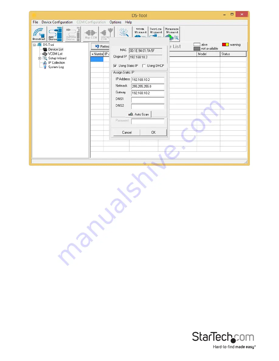
To add a virtual COM port, please use the VCOM Wizard and follow the steps.

Using the Logging Feature

To use the device server’s Logging Feature within the DS-Tool, follow the steps below:
1.  In the navigation menu on the left side of the window, under 

Device List

, click the 

IP address for the applicable connected device.

2.  To use the current machine for logging, under 

System Log Settings

, click 

Using 

Current Host’s Log Server

.

3.  In the navigation menu on the left side of the window, click 

System Log

.

Summary of Contents for NETRS232485

Page 1: ...startech com FR Guide de l utilisateur fr startech com ES Gu a del usuario es startech com IT Guida per l uso it startech com NL Gebruiksaanwijzing nl startech com PT Guia do usu rio pt startech com...

Page 2: ...ealer or an experienced radio TV technician for help This device complies with part 15 of the FCC Rules Operation is subject to the following two conditions 1 This device may not cause harmful interfe...

Page 3: ...troduction 2 Packaging Contents 2 System Requirements 2 DB 9 Connector Pinout 3 DIP Switch Configuration 3 Installation 4 Hardware Installation 4 Software Installation 4 Operation 5 Using the DS Tool...

Page 4: ...1 LED for PWR1 2 LED for PWR2 3 LED for Ethernet Port 1 4 LED for Ethernet Port 2 5 LED for Serial Port Side 1 1 Terminal Block PWR1 12 48V DC 2 Power Jack PWR2 12 48V DC 3 2x Ports RJ45 10 100 Side 2...

Page 5: ...Packaging Contents 1x Serial over IP Device Server 1x DIN Rail Kit 1x Wall Mount Kit 1x Software CD 1x Installation Guide System Requirements Windows 8 32 64bit 7 32 64 Vista 32 64 XP 32 64 2000 Windo...

Page 6: ...nout DIP Switch Configuration DIP 1 DIP 2 Termination Configuration ON ON Termination for long distance 4 wire RS485 422 ON OFF Reserved OFF ON Termination for long distance 2 wire RS485 OFF OFF No te...

Page 7: ...ound is heard Installation on a Wall 1 Remove the DIN rail kit if it is installed on the unit 2 Install the wall mount panel included using the 3 screws found in the package 3 Mount the unit on the wa...

Page 8: ...o the DS Tool on the Windows Firewall 3 Once the utility opens click the Broadcast button to detect the device server The default IP address of the device is 192 168 10 2 4 Once detected click the che...

Page 9: ...eature within the DS Tool follow the steps below 1 In the navigation menu on the left side of the window under Device List click the IP address for the applicable connected device 2 To use the current...

Page 10: ...Instruction Manual 7 4 The log data is displayed in the DS Tool under Log Message...

Page 11: ...rotocols RS232 422 485 Ethernet Link Speed 10 100 Mbps Maximum Baud Rate 460 8 Kbps Power Input Terminal Block 12 48VDC in 3 pin 12 48VDC center positive power jack plug Enclosure Material Metal Opera...

Page 12: ...returned for repair or replacement with equivalent products at our discretion The warranty covers parts and labor costs only StarTech com does not warrant its products from defects or damages arising...

Page 13: ...ts and we quickly deliver them wherever they need to go Just talk to one of our tech advisors or visit our website You ll be connected to the products you need in no time Visit www startech com for co...

Reviews: