

Version 2.17.4
E9
V
2
Additional connection options
Configuring the security-telematic system
1.
Disarm security system.
2.
Switch ignition Off, if it is On, then press service button 7 times.
3.
Switch ignition On.
4
. 7 LED flashes of service button and 7 buzzer sounds will follow.
5
. Then 2 LED flashes of service button and 2 buzzer sound signals will follow, confirming entry into Registration mode.
6.
Enter the owner authorization code using car OEM buttons with a pressing interval no more than 3 seconds. Every button
pressing should be followed by a single service button LED flash.
The owner authorization code consists of a code sequence containing from 3 to 30 OEM buttons pressing. The list of supported
OEM buttons is available at
can.starline.ru
. If a service button LED flash does not follow after pressing of OEM button, so this
button is not supported for this car.
7.
In 3 seconds after the code entry 2 short LED flashes and 2 buzzer sound will follow, confirming the code successful registration.
8.
Enter the owner authorization code again.
9.
If the code is recorded properly, 2 LED flashes and 2 short buzzer sound will confirm. If the code recording is failed, so 4 short
buzzer sounds will follow, in this case repeat steps 6-8.
10.
In 10 sec switch ignition Off to exit the Registration mode.
11.
An exit from Registration mode will be confirmed by double LED flashes and buzzer sounds and then additional signals in
amount of total registered tags, pagers and smartphones will follow.
12.
Write down and memorize this entered Authorization code.
Switch to device registration mode
1.
Disarm the security system.
2.
Switch ignition Off if it is On.
3.
Press the valet button 7 times.
4.
Switch ignition On. 7 light LED flashes of service button and 7 buzzer sounds will follow.
5.
2 short LED flashes and buzzer sounds will confirm entry into the Registration mode.
2-way remote control (pager) registration
6.
Press pager buttons 1 and 2 shortly.
7.
In 3 seconds successful registration will be confirmed by a short beep sound of pager, 2 LED flashes of service button and 2 buzzer
sound signals. If a pager is not registered, 4 beep sounds of pager will follow.
8.
Repeat points 6-7 for each pager.
Bluetooth tags (transponders) registration
9.
Remove battery from tag.
10.
Hold a tag button pressed and insert battery back. A tag LED will turn red.
11
. Release button, a series of red flashes will follow.
12.
In 10 seconds successful registration will be confirmed by green LED flash, 2 flashes of service button LED and 2 buzzer sounds. If
tag is not registered LED will turn red.
13.
Repeat points 9-12 for all remaining tags.
Smartphone registration
14.
Register a smartphone* with use of the free StarLine mobile App.
Exit from the device registration mode
15.
In 10 seconds switch ignition Off to exit the registration mode. An exit from Registration mode will be confirmed by double LED
flashes and buzzer sounds and then additional signals in amount of total registered tags, pagers and smartphones will follow.
* The iOS and Android smartphone with Bluetooth Smart 4.2 and above are supported.
Programming an owner authorization code (with car buttons)
New devices registration
NOTE!
At registration of new tags and smartphones all previously registered tags and smartphones will be erased from
memory. So the existing devices should be registered simultaneously in one cycle with all the new devices. In total up to 5
Bluetooth devices can be registered in the system main unit.
When new RF pagers are registered, all previously registered pagers will be erased from memory. So the existing pagers
should be registered simultaneously in one cycle with all the new pagers.
In total, up to 4 RF pagers can be registered in the system main unit.
NOTE!
The tags included in the delivery set are already registered in the main unit and are in the transport mode,
i.e. off. Pressing the tag button in this mode will be indicated by a green and red flashes of the built-in LED. Prior to
operation press the tag button several times until the LED color turn to green (regular mode).
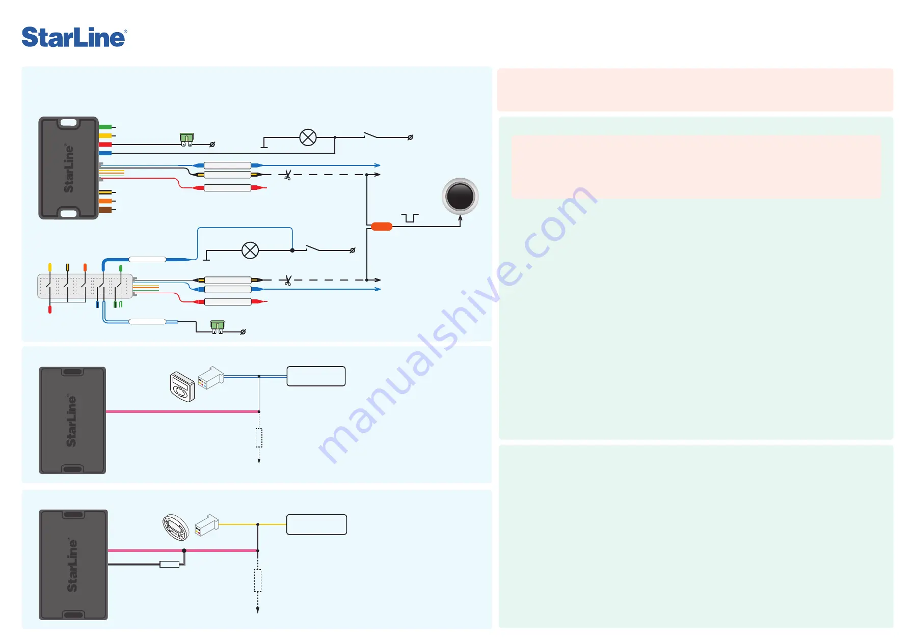
Power module V1
Power module V2
+ 12 V
30 A
+ 12 V
+ 12 V
START
STOP
E N G I N E
blue
black-yellow
red
10-50 kOhm
+12 V
blue-white
Heater
control unit
pink
10-15 kOhm
+12 V
51-75 kOhm
Heater
control unit
pink
gray-black
blue-white
blue
+ 12 V
30 A
blue
red
black-yellow
or
Brake trigger switch
Brake trigger switch
Brake lights lamp
Brake lights lamp
Push-to-start
button
To the blue wire
of connector Х2
To the blue wire
of connector Х2
To the red wire
of connector Х2
To the red wire
of connector Х2
To the black-yellow
wire of connector X2
To the black-yellow
wire of connector X2
Negative control pulse
1.
In StarLine Master program set X2:6 blue wire as "Engine start: simulate brake or clutch pedal" and X2:14 black-yellow wire
as "Engine start: PTS button".
2.
Connect wires according to diagram for corresponding power module.
Diagram of starting circuit connection on cars with PTS button
Webasto heater connection with digital bus control
1.
In StarLine Master software set the pink
output wire of X1 connector as “Webasto
heater control via digital bus”, the gray-black
wire – as “Webasto preheater start control via
digital bus".
2.
In “Engine start” section “Starting preheater”
enable “Permission for preheater operation”.
For the point “Start type of preheater” select
option “Webasto via digital bus”.
3.
Connect the wires according to the diagram.
yellow
Eberspächer heater connection with digital bus control
1.
In StarLine Master program set the pink
output wire of X1 connector as “Eberspacher
preheater control via digital bus”
2.
In “Engine start” section “Starting preheater”
enable “Permission for preheater operation”.
For the point “Start type of preheater” select
option “Eberspacher via digital bus”.
3.
Connect the wires according to the diagram.


