Starke STK Series Owner'S Manual Download Page 4

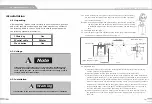
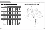
2. Main  specifications

2.1  Table of specifications

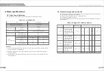
The specifications  in  the following  table are  applicable to  all  electric chain  hoists.

Table 2.1  Specifications 

Item 

Specification 

Range of working  humidity(%) 

85  or below85 

Range of working temperature(

°

C) 

-20-+40

Hoist 

Ip54 

Protection class 

Push button 

Ip54 

Power supply 

3 phase,200-600V,50/60Hz 

Single speed hoist 

81 

Noise degree(dB) 

Double speed  hoist 

81 

Limit working load 

Nominal  diameter(mm)  Chain  Internal  length(mm) 

0.St

6.3 

19 

Chain 

1t,2t,3t 

7.1 

21 

specifications 

1.St,2t,3t

10.0 

30 

2.St,3t,St,7.St

11.2 

34 

Remarks 

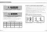
(1)  If your working temperature  and  humidity are  out the  range of the value  in  the table,  please

ask your distributor for related  data.

(2)  Expected  operation  ways:The  hoist is  designed  to  vertically  lift  in  normal  atmosphere and 

working  conditions.

(3)  The standard  of noise degree  is  the value  measured  at  1 meter from  the  machine  under the

normal  operation.

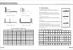
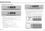
2.2  Machine degree and  service life 

The service and  safety of the electric chain  hoist can  be  guaranteed  only  under the condition 

that it  is  operated  according to the following. 

The  design  of the  hoist conforms to  lAm of FEM(Table  2.21) 
The  description  is  detailed  in  table  2.2 

The average operation  hours  per day  and  total  operation  hours are  calculated on  the  basis of 

load  distribution. 

Table 2.2  Categories of machine degrees 

Load types 

Definition 

Cubic meters 

Average operation  hours per day(hours) 

Value represented 

The  mechanism and 

parts are  frequently 

l(light) 

under light  load,  and 

K:<::;0.50 

:<::;2 

2-4

4-8

8-16

:<::;16 

>16 

there is  no  max.  load 

other than  exceptional 

conditions. 

The  mechanism and 

parts are  frequently 

2(middle) 

under light  load,  but 

0.S0<K:<::;0.63 

:<::;1 

1-2 

2-4

4-8

8-16 

:<::;16 

also  under max.  load 

with  low  frequency. 

The  mechanism and 

3(heavy) 

parts are frequently 

0.63<K:<::;0.80 

:<::;0.5 

0.5-1 

1-2 

2-4

4-8  8-16

under middle  and 

heavy  load. 

The  mechanism and 

parts are frequently 

0.80<K:<::;1.00 

:<::;0.25 

0.25-0.5 

0.5-1 

1-2 

2-4

4-8

(Super-heavy) 

under max.  or nearly 

max.  Load. 

1Bm 

1Am 

2m 

3m 

4m 

Sm 

llilll 

Summary of Contents for STK Series

Page 1: ...STARKE STK SERIES ELECTRIC CHAIN HOIST OWNER S MANUAL STARKEAMERICA COM ...

Page 2: ... should read through and be familiar with the operation manual and precautions before operation to ensure the safe operation If any part of the manual has the alarming signs as indicated at the right and left and the part is underlined it indicates that the part is vital safety description or precaution And operators must fully followed otherwise it may endanger the operators or others or property...

Page 3: ...1 1 Preface The manual can assist you in correct installing operating and maintaining your electric chain hoist ensure your hoist to operate safely with the highest efficiency Before you use the hoist please read through the manual to know about the correct procedure and operation as well as preventative maintenance to guarantee you to have faithful and reliable service In order to provide the par...

Page 4: ... normal operation 2 2 Machine degree and service life The service and safety of the electric chain hoist can be guaranteed only under the condition that it is operated according to the following The design of the hoist conforms to lAm of FEM Table 2 21 The description is detailed in table 2 2 The average operation hours per day and total operation hours are calculated on the basis of load distribu...

Page 5: ...to control the circuit not to work and protect the electric motor from being burned in case of wiring error in the power supply 4 Limit switch It is installed where the weights is lifted on and off to make the motor stop automatically so as to prohibit the chains from exceeding for safety 5 Emergency stop switch optional The button is used to stop the hoist in emergency It is red mushroom shaped p...

Page 6: ...33 343 450 320 c j 5 9 48 34 c j 3 6 138 265 10 3 3 810 627 302 370 205 c j 5 9 48 34 c j 3 6 138 265 7 1 2 5 855 733 343 450 325 1 6 0 48 42 I 4 1 157 304 11 2 Capacity Chain fall Ton A 1 0 5 525 566 1 1 520 627 2 1 580 566 1 1 5 610 733 1 2 610 733 2 2 685 627 1 2 5 670 733 1 3 670 733 2 3 770 733 3 3 810 627 2 5 855 733 2 5 Electric trolley R 0 0 0 0 0 s Unit mm B D E I K L N 266 285 165 I 3 1 ...

Page 7: ... Be sure that the motor has been completely stopped before operating in the reverse direction 6 When finished operation to keep the control cable and the lower hook vertically and statically 7 When lifting the weights must be kept balance Never lift the weight which are not in balance 8 It is forbidden to drag the weights horizontally see Fig 3 2 9 It is forbidden to lift the weights by using the ...

Page 8: ... Assemble chain bag Fig 4 1 4 3 3 Link the power supply and operate the push button the procedure should be performed by professional trained person Fig 4 2 Fig 4 1 lm 1 Sm Power cable pulley R S T Electrical box Contactor 0 W O N O F F red Earth black yellow and green or green Fig 4 2 4 3 4 Operation test a Press the push button to lower the hoist until the limit spring touches the limit switch a...

Page 9: ...ut the suspension shaft with inner adjusting spacer inside after putting the spacers the total width should be about half of the width of traversing beam 3 As the Fig 4 6 shown do installation step by step Firstly install suspender Tinto hoist body and insert the shaft into suspender T 4 Secondly install the adjusting spacers on it Put side plate S between trolley wheel and electric case And fix w...

Page 10: ...Fig 4 8 3 Firstly support one side plate G or S then push the other side plate S or G with strength to prevent its shedding from rail Keep the wheel rail and the traveling rail at the same level Trolley with the hoist mounting to traversing rail 4 Remove the bolt from the hole B insert it to the hole A and fix it with split pin 5 Operation After the above mentioned test and operation testing the h...

Page 11: ...y inspection A Warning In maintenance please use the original parts recommended by the manufacturer a Chain Any distorted extended or worn chain will not be good locked with chain wheel result in the breakdown or disengaging of the chains To ensure the safe and normal operation the internal length and width external width of the chain must be checked monthly If in the following situation the chain...

Page 12: ...215 X 215 X 500 canvas Other 6 3 7 1 20 I Steel 10 0 11 2 IIIDI Chain gauge to regularly measure the wearing and elongation 1 It is convenient to measure with chain gauge provided by the manufacturer 2 As shown in Fig 6 3 and Fig 6 4 measure the chain internodal distance and diameter with the chain gauge 3 Every link should be measured and it must be replaced with a new one if any of the links is ...

Page 13: ...0V 24 36 48V with emergency stop 23 Electric specifications are as follow a 3 phases b Frequency 50Hz 60Hz c Single voltage or dual voltage F Dual voltage 50Hz 220V 380V 220V 440V 60Hz 230V 460V Single voltage 220V 600V 2 Points single speed With emergency stop L1 L2 L3 PE K1 A B 380V Ov T C Anti phase 24 36V protector K2 KM1 3 5 5 3 1 KM2 ES 4 6 6 4 S82 L S1 KM2 S83 L S2 KM1 E L S Limit Switch KM...

Page 14: ...2 L 3 L S Limit Switch KM A C Contactor ES Emergency Stop SB Push botton 6 Points single speed With emergency stop 380V T G 24 36V CJ tPH KM3 Ki 12 3 Is 1 1 3 1s 3 I s I 1 I 3 I s KM4 KM5 KM6 4 I 6 1 2 l 4 I 6 12 I 4 I 6 1 2 I 4 I 6 KM1 3 5 I KM2 2 I 4 6 1 6 4 1 2 ES SB2 L S1 r KM21 KM1 SB3 L S2 KMl KM2 SB4 KM41 n KM3 rE E KM3 KM4 E Lifting motor KM6 KM5 Trolley motor End carriage motor 6 SB7 KM 5...

Page 15: ...k assembly parts list 3 7 5ton 30 Vl 3Gearboxassemblydrawing 3 1 Vl 3 Gear box assembly parts list 32 Vl 4Chainassemblydrawing 33 Vl 4 Chain assembly parts list 34 Vl 5 Electrical box assembly drawin j 35 Vl 5 Electrical box assembly parts list 36 Vl 7 Electric trolley assembly drawing 37 Vl 7 Electric trolley assembly parts list 38 Vl 8 Hand trolley assembly drawing 39 Vl 8 Hand trolley assembly ...

Page 16: ...4 4 4 4 4 23 Motor shell 1 1 1 1 1 1 1 1 1 1 1 1 1 1 1 1 24 Socket head cap screw 4 4 4 4 4 4 4 4 4 4 4 4 4 4 4 4 25 Spring type straight pin 2 2 2 2 2 2 2 2 2 2 2 2 2 2 2 2 26 Gasket A 1 1 1 1 1 1 1 1 1 1 1 1 1 1 1 1 27 Upper hook bearing bush 2 2 2 2 2 2 2 2 2 2 2 2 2 2 2 2 28 Hex nut 4 4 4 4 4 4 4 4 4 4 4 4 4 4 4 4 29 Spring washer 4 4 4 4 4 4 4 4 4 4 4 4 4 4 4 4 30 Motor bottom plate 1 1 1 1 1...

Page 17: ...2 2 2 2 2 I I 2 2 2 2 I I I I 8 Chain limit spring 1 1 1 1 1 1 1 1 2 2 1 1 1 1 2 2 2 2 9 Chain 3 Sm 3 5m 3 5m 3 5m 3 5m 3 5m 3 5m 3 5m 7m 7m 3 5m 3 5m 3 5m 3 5m 7m 7m 7m 7m 10 Self locking nut 2 2 2 2 2 2 2 2 I I 2 2 2 2 I I I I 1 1 Slotted spring pins I I I I I I I I 1 1 I I I I 1 1 1 1 12 Outer hexagonal shell I I I I I I I I 4 4 I I I I 4 4 4 4 13 Lower load block shell I I I I I I I I 2 2 I I ...

Page 18: ... 8 Hexnut 6 6 9 Spring washer 6 6 10 Stent motherboard under 1 1 1 1 Chain guiding for inlet and outlet 1 1 12 Chain 10 5m 10 5m 13 Limit spring 1 1 14 Guide chain body 1 1 15 Chain bolt 1 1 16 Chain locking block 1 1 17 Locking block of gasket 2 2 18 Hex slotted nut 1 1 19 Split pin 1 1 20 Locking block of shaft 1 1 2 1 Stent vice board under 1 1 22 lower hook chain wheel shaft 1 1 23 Spring stra...

Page 19: ...1 1 8 Spring plate fixing sleeve 1 1 1 1 1 1 1 1 1 1 1 1 1 1 1 1 9 Disc spring plate 2 2 2 2 2 2 2 2 2 2 2 2 2 2 2 2 10 Braking plate 2 2 2 2 2 2 2 2 2 2 2 2 2 2 2 2 1 1 Intermediate gear 1 1 1 1 1 1 1 1 1 1 1 1 1 1 1 1 12 Gear fixing plate 1 1 1 1 1 1 1 1 1 1 1 1 1 1 1 1 13 Gear shale 1 1 1 1 1 1 1 1 1 1 1 1 1 1 1 1 14 Deep groove ball bearing 1 1 1 1 1 1 1 1 1 1 1 1 1 1 1 1 15 Deep groove ball b...

Page 20: ... 1 1 1 1 1 1 1 1 1 1 1 8 Oriented pulley 1 1 1 1 1 1 1 1 1 1 1 1 1 1 1 1 9 Spring washer 2 2 2 2 2 2 2 2 2 2 2 2 2 2 2 2 10 Socket head cap screws 2 2 2 2 2 2 2 2 2 2 2 2 2 2 2 2 1 1 Limit switch spring 1 1 1 1 1 1 1 1 1 1 1 1 1 1 1 1 12 Guide limited pin 1 1 1 1 1 1 1 1 1 1 1 1 1 1 1 1 13 Elastic cylindrical pin 1 1 1 1 1 1 1 1 1 1 1 1 1 1 1 1 14 Limit guide frame 1 1 1 1 1 1 1 1 1 1 1 1 1 1 1 1 ...

Page 21: ...1 1 1 1 1 1 1 1 1 8 Connecting shaft assembly for control switch 1 1 1 1 1 1 1 1 1 1 1 1 1 1 1 1 9 Round cross screw Ms 10 2 2 2 2 2 2 2 2 2 2 2 2 2 2 2 2 10 Electrical installation plate 1 1 1 1 1 1 1 1 1 1 1 1 1 1 1 1 1 1 Spring Washer ij 6 4 4 4 4 4 4 4 4 4 4 4 4 4 4 4 4 12 Round cross screw Ms 15 4 4 4 4 4 4 4 4 4 4 4 4 4 4 4 4 13 Reverse bracket B 1 1 1 1 1 1 1 1 1 1 1 1 1 1 1 1 14 Spring Was...

Page 22: ...IST 17 socket head cap screw 1 1 1 1 1 1 49 electric control case shell gasket 1 1 1 1 1 1 18 spring washer 4 4 4 4 4 4 50 electric control case shell 1 1 1 1 1 1 19 gearoox 4 4 4 4 4 4 51 spring washer 4 4 4 4 4 4 Every Type Hoist Use Quantity Item Spare Parts Name 0 51 11 2 1 3 1 5 1 7 51 20 f 1 1 I I l J V V c t C I Jt J 1 1 1 1 1 1 52 socket head cap screw 4 4 4 4 4 4 1 Circlip for shaft 4 4 4...

Page 23: ... is worn or deteriorated 3 Install a proper plug gasket or replace a new gasket lll1ill 10 Instructions of using and inspecting for electric chain hoist Caution When using the electric chain hoist conduct in accordance with the following items 1 Confirm that the ISO level of electric chain hoist in use is in accordance with using conditions 2 No overloading 3 Electric chain hoist must be equipped ...

Reviews: