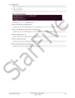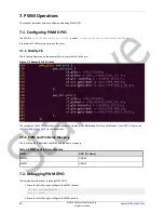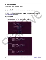
| 8 - UART Operations
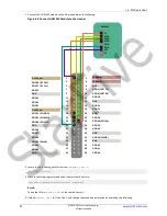
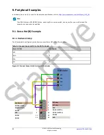
1. Connect the jumper wires from the USB-to-Serial Converter to the 40-Pin GPIO header of the VisionFive 2 as follows.
Figure 8-4 Connect the Converter to the Header
1
3
5
7
9
11
17
19
23
27
31
35
13
15
21
25
29
33
37
39
2
4
6
8
10
12
18
20
24
28
32
36
14
16
22
26
30
34
38
40
5V Power
5V Power
GND
GPIO5 (UART TX)
GPIO6 (UART RX)
GPIO38
GPIO51
GND
GPIO49 (SPI CE0)
GPIO40
GPIO46 (PWM0)
GPIO36
GND
GPIO54
GPIO50
GPIO56
GND
GND
GPIO61
GPIO44
3.3V Power
GPIO58 (I2C SDA)
GPIO57 (I2C SCL)
GPIO55
GND
GPIO42
3.3V Power
GPIO52 (SPI MOSI)
GPIO48 (SPI SCLK)
GPIO45
GPIO39
GPIO63
GPIO43
GPIO47
GPIO53 (SPI MISO)
GND
GPIO37
GPIO59 (PWM1)
GPIO60
GND
3Y3
RXD
GND
+5V
TXD
3Y3
RXD
GND
+5V
TXD
IC
2. Connect the other end of the USB-to-Serial Converter to your device (Windows/Mac/Linux).
8.2.2. Debugging UART Send and Receive Functions
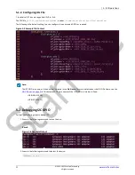
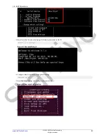
1. Configure VisionFive 2 Minicom:
sudo minicom -s
2. Select
Serial port setup
, and configure Minicom as follows:
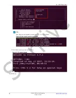
Figure 8-5 Example Configuration
29
© 2018-2022 StarFive Technology
All rights reserved
StarFive


