background image

– 2 –

2. Unpacking and Installation

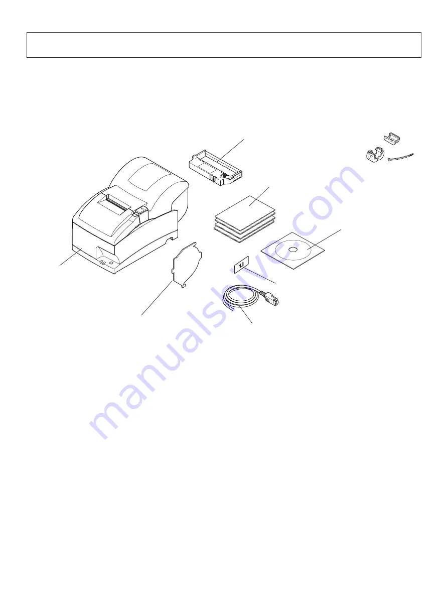
2-1. Unpacking

After unpacking the unit, check that all the necessary accessories are included in the package.

Note:

 The ferrite core and fastener provided with your 

printer depend on your printer configuration.

Fig. 1-1 Unpacking

If anything is missing, contact the dealer where you bought the printer and ask them to supply 

the missing part. Note that it is a good idea to keep the original box and all the packing materials 

just in case you need to pack the printer up again and send it somewhere at a later date.

Printer

Switch blind

Power cord

Roll paper guide

Ribbon cartridge

Setup sheets

CD-ROM

Note

Summary of Contents for SP717R Series

Page 1: ...DOT PRINTER SP717R 747R SERIES Paper Rewinder Model Hardware Manual...

Page 2: ...C Rules These limits are designed to provide reasonable protection against harmful interference when the equipment is operated in a commercial environment This equipment generates uses and can radiate...

Page 3: ...e Roll Paper Guide 19 6 Control Panel and Other Functions 22 6 1 Control Panel 22 6 2 Basic Indicators 22 6 3 Errors 23 6 4 Adjustment Mode 25 7 Preventing and Clearing Paper Jams 31 7 1 Preventing Pa...

Page 4: ...e Specifications 51 13 2 Ethernet Interface Specifications 51 13 3 Wireless LAN Interface Specifications 51 14 Memory Switch Settings 52 15 Release History 53 Please access the following URL http www...

Page 5: ...l equipment etc SP7 1 7 M D R Color None Standard color off white GRY Gray Rewinder None Without rewinder Standard R With rewinder Interface D Serial interface RS 232C C Parallel interface U USB E Eth...

Page 6: ...r printer configuration Fig 1 1 Unpacking If anything is missing contact the dealer where you bought the printer and ask them to supply the missing part Note that it is a good idea to keep the origina...

Page 7: ...d free of dust P Make sure that the printer is connected to a reliable power outlet It should not be on the same electric circuit as copiers refrigerators or other appliances that cause power spikes P...

Page 8: ...pment but should be treated with a modicum of care in order to avoid malfunctions For example 1 Keep your printer in a comfortable environment Roughly speaking if you feel comfort able then the enviro...

Page 9: ...Features one control switch and two indicators to indicate printer status Interface connector Connects the printer with host computer Power switch Turns printer power on and off Peripheral unit drive...

Page 10: ...cable to a parallel port of your PC 4 1 2 RC 232 Interface Cable Connect the RC 232 interface cable to a RS 232 port of your PC 4 1 3 USB Interface Cable Connect the USB interface cable to a USB port...

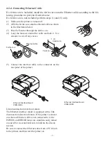
Page 11: ...make sure the power cable plug is disconnected from the AC outlet 4 2 1 Parallel Interface Cable 1 Make sure the printer is turn off 2 Affix the ferrite core onto the cable as shown in the illustrati...

Page 12: ...the printer is turned off Also make sure the power cable plug is disconnected from the AC outlet 2 Connect the interface cable to the connector on the rear panel of the printer 3 Tighten the connector...

Page 13: ...er Link disconnection detection feature The Ethernet interface model is equipped with a link disconnection detection feature If the printer is turned on when an Ethernet cable is not connected to it t...

Page 14: ...a Windows 7 1 Turn ON the power to your PC to start Windows 2 InsertthesuppliedCD ROM DriversandUtilities into the CD ROM drive 3 Follow the instructions that appear on the screen 4 The dialog shown i...

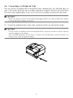
Page 15: ...our needs CAUTION Make sure that the printer is turned off and unplugged from the AC outlet and that the computer is turned off before making connections 1 Connect the peripheral drive cable to the co...

Page 16: ...its voltage matches that of the AC outlet Also make sure the plug on the power cord matches the AC outlet 2 If the power cord is not attached to the printer plug the appropriate end into the AC inlet...

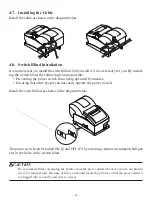
Page 17: ...t you unplug the printer from the power outlet whenever you do not plan to use it for long periods Because of this you should locate the printer so that the power outlet it is plugged into is nearby a...

Page 18: ...ated by mistake Ensuring that other people can not easily operate the power switch Install the switch blind as shown in the diagram below The power switch can be turned ON and OFF O by inserting a nar...

Page 19: ...you not put your hand in the paper outlet slot while printing is in progress never put your hand into the outlet even when printing is not in progress 3 Place the ribbon cartridge in the direction sh...

Page 20: ...be extremely hot On the auto cutter model there is a paper cutter at the paper outlet slot Never allow your hand to come in contact with the cutter blade 2 Load the paper roll in the direction as show...

Page 21: ...the slit 6 Wind the paper roll twice around the spool Note Wind the paper roll without loosening it while the right end of the paper roll is in contact with the spool rim 7 As you load the spool onto...

Page 22: ...ter cover 0 Cut the leading edge of the roll paper as shown Note When the paper end mark appears on the reverse of the paper replace the paper roll before it runs out n Opening the printer cover befor...

Page 23: ...the attached roll paper guide in the groove in the printer The setting for memory switch 2 A and 2 B must be changed to change the print width For instructions on setting the memory switch please refe...

Page 24: ...produces smoke a strange odor or unu sual noise Immediately unplug the equipment and contact your dealer for advice P Never attempt to repair this product yourself Improper repair work can be dangero...

Page 25: ...connect wiring to the external drive connector if there is a chance it may carry peripheral voltage P Do not operate the cover open lever while pressing on the printer cover with your hand P Do not p...

Page 26: ...D 1 POWER lamp Green LED 1POWER lamp Green LED Lights when the power is ON 2FEED button Press the FEED button to feed roll paper 3ERROR lamp Red LED Indicates various errors in combination with POWER...

Page 27: ...13 sec 0 5 sec 7 Mechanical error other than cutter error On Flashes On 0 25 sec Off 0 25sec 2shortbeeps 0 13 sec 0 5 sec 8 Blackmarkdetec tion error On Flashes On 0 5 sec Off 0 5 sec 3shortbeeps 0 13...

Page 28: ...NQ n command when in the ESC POS mode When the error occurs STAR Mode Non recoverable error ESC POS Mode Recoverable error 9 For paper jam errors Clear the jammed paper and change the paper roll if ne...

Page 29: ...down for 2 more seconds 4 The Black Mark Sensor Alignment Mode is entered by releasing the FEED switch after the buzzer sounds four times Refer to Section 6 4 4 Holding down for 2 more seconds 5 The N...

Page 30: ...performed to print the Ver No and printer settings ASCII printing will be repeatedwhentheFEEDswitchisheldcontinuouslyattheendofASCII printing Theself printing mode will end automatically when the FEE...

Page 31: ...llowing This is caused when mechanical parts of the printer get out of alignment This happens only rarely and you may never experience it at all throughout the life of the printer If you do have probl...

Page 32: ...anged Then repeat step 3 Backward Press and hold the FEED switch for 2 to 4 seconds The buzzer will beep and the printer will print a pattern in which the forward is adjusted more leftward of the pres...

Page 33: ...de This function allows you to check if a control code sent to the printer by the program being used is correct or not The last line is not printed if its data is less than one full line However if th...

Page 34: ...right Therefore secure the printer by placing your hand on the printer before performing this operation 3 Since it is adjusted by rotating the volume VR2 check the position of the volume Prepare a sma...

Page 35: ...uto cutter to the home posi tion by following the instructions provided in Section 7 3 3 Remove the jammed paper CAUTION Take care not to damage the printer when removing the jammed paper 4 Position t...

Page 36: ...diately after printing be sure not to touch it On an auto cutter model a paper cutter is located at the paper outlet slot Be careful not to touch the cutter blade 4 Open the front cover by holding the...

Page 37: ...insert a Phillips screwdriver into the Phillips screw hole on the side of the cutter and turn it in the direction of the arrow shown below in order to return the cutter to its normal position 8 Reins...

Page 38: ...cables which meet the following specifications Peripheral Drive Connector Drive circuit The recommended drive unit is shown below Drive Output 24V Max 1 0A TR1 TR2 Transistor 2SD1866 or equivalent R1...

Page 39: ...ires red black 3 Never use the external buzzer command if you connect a device such as a cash drawer other than an external buzzer It could damage the connected device and the printer circuit Refer to...

Page 40: ...tion feed Paper feed speed Approx 141 mm sec Paper specifications Paper type Ordinary bond and carbonless copy paper 2P Paper width 76 0 5 mm 3 0 inches 57 5 0 5 mm 2 25 inches 69 5 0 5 mm 2 75 inches...

Page 41: ...ibbon life RC700BR Black 1 500 000 characters Red 750 000 characters RC700B Black 3 000 000 characters Overall dimensions 160 W 288 D 184 5 H mm 164 184 5 288 160 245 Weight Approx 3 5 kg Tear bar mod...

Page 42: ...to 70 C Storage humidity 5 to 95 RH at 40 C without condensation Mechanical life 10 million lines except head life and auto cutter Print head life 150 million characters Auto cutter life 1 million cut...

Page 43: ...will become effective when the power switch is set to on again The following is the procedure for changing the settings on DIP switches 1 Make sure the printer is turned off 2 Remove the screw from th...

Page 44: ...valid 1 7 Reserved 1 8 Print head model 3 18 pin wire 9 pin wire 1 The factory settings for enabling disabling the auto cutter are as follows Models without auto cutter Invalid Switch 1 2 on Models wi...

Page 45: ...rial interface board unit Then secure it with the screws 6 Turn on the printer and all components connected to it The factory settings of DIP switch are all on except for switches 7 and 8 DIP SW 2 Swi...

Page 46: ...h for one to five seconds while running under normal operating mode The green and red LEDs will flash with a regular pattern After that push the switch once again in that state to turn OFF both of the...

Page 47: ...tch are all off LED Display Green Lights when pockets are received Note This product contains a built in wireless device and can only be used in the following countries USA UK France Ireland Belgium G...

Page 48: ...l the ferrite core onto the peripheral drive cable to prevent radio interference Use the fer rite core only for the wireless LAN model in the EU 1 Install the ferrite core onto the peripheral drive ca...

Page 49: ...45 Connecting the peripheral drive cable Connect the peripheral drive cable to the connector on the printer Then connect the other end of the cable to the peripheral drive circuit Except for EU EU onl...

Page 50: ...onous serial interface 2 Baud rate Selectable from 4800 9600 19200 38400 bps Refer to 10 DIP Switch Setting 3 Word length Start bit 1 bit Data bit 7 or 8 bits selectable Parity bit Odd even or none se...

Page 51: ...communication mode status of this signal is not checked Dip switch 2 7 ON This is an externally reset signal A mark above 1 ms pulse width engages reset 7 SG Signal ground 8 19 N C Not connected 20 D...

Page 52: ...witch 2 8 ON This is an externally reset signal A space above 1 ms pulse width engages reset 11 3 Interface Connections Refer to the interface specifications of the host for details on connecting to i...

Page 53: ...Data1 4 In Data2 Data2 5 In Data3 Data3 6 In Data4 Data4 7 In Data5 Data5 8 In Data6 Data6 9 In Data7 Data7 10 Out nAck PtrClk 11 Out Busy PtrBusy Data3 7 12 Out PError AckDataReq Data2 6 13 Out Sele...

Page 54: ...e nInit signal 31 pin Reset can be made from 31 pin nInit signal of the interface by memory switch setting Factory setting is reset In addition when reset has been enabled by 31 pin nInit signal it ca...

Page 55: ...n modular Note Factory set login password for administrator One of the following protocols may be used for changing the settings on this product HTTP web TELNET or FTP To do so it is necessary to log...

Page 56: ...emory switches see the separate Specification Manual The table below shows the factory settings for the memory switches Memory Switch Hexadecimal Code 0 0000 1 0000 2 0080 3 0000 4 0000 5 0000 6 0000...

Page 57: ...53 15 Release History Rev No Date Month Day Year Contents Rev 1 0 08 30 2009 New Release Rev 1 1 07 30 2010 Page 9 Added the description about the Ethernet interface board IFBD HE08 Rev 1 2 09 29 2011...

Page 58: ...URL http www starmicronics com support...

Reviews: