background image

12 


620-7991 Rev 002 


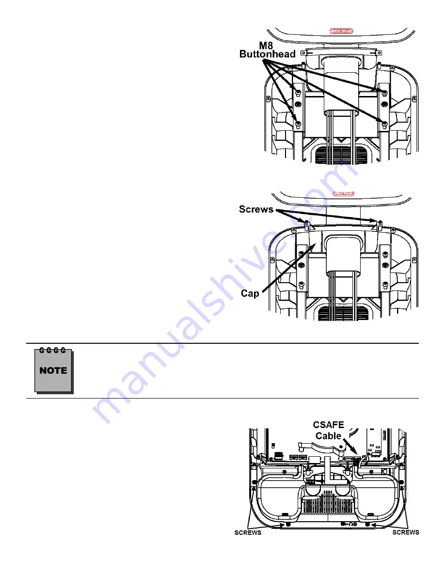
STEP 8.  

Adjust the cap with the grommet into place. Using 
the  5mm  Hex  key,  tighten  the  M8  buttonhead 
screws  to  190  lb-in  (21.5  N-m)  of  torque.  Take 
the  (2)  Phillips  head  screws  you  removed  from 
the  original  cap  and  snugly  tighten  screws  down 
using a #2 Phillips screwdriver. 

Check the back side of the display to see that the cap is seated properly. If not, loosen 
the two Phillips Head Screws, adjust the cap and then retighten the screws. 

STEP 9.  

Using  a  #2  Phillips  head  screwdriver,  remove 
the (4) screws that hold bottom side of the dis-
play console on. Next remove the bottom cover. 

Caution:

  When  removing  bottom  cover,  gently 

disconnect  the  CSAFE  cable  from  the  back  of 
the display board. 

Retain screws for later use. 

STEP 7.  

Mount  the  PVS  assembly  on  the  mounting 
bracket,  then  thread  the  (4)  M8  buttonhead 
screws  through  the  PVS  mounting  bracket  into 
the display mount.  Do not tighten the screws yet. 

 
Note: 

 (2) of the screws are in the PVS kit, (2) retained from 
step 5

.


Summary of Contents for E-RBi

Page 1: ...620 7991 Rev 002 STAR TRAC FITNESS PERSONAL VIEWING SCREEN USER S MANUAL E SERIES E UBi E RBi E STi E TBTi E TRi STAR TRAC 14410 Myford Road Irvine CA 926060 USA ...

Page 2: ...2 620 7991 Rev 002 ...

Page 3: ...u Options 36 Adjusting Sound Menu Options 37 Adjusting Time Menu Options 38 Adjusting System Options Menu 40 Adjusting Lock Menu Options 41 Adjusting Channel Menu Options 43 FAQ s and Troubleshooting 46 Cleaning the PVS 46 Troubleshooting 46 Headphone Jack Replacement 48 Regulatory Information 49 Copyright 2010 Star Trac by Unisen Inc All rights reserved including those to reproduce this book or p...

Page 4: ...des an overview of each section within the manual Before You Get Started Provides guidelines to help you have a successful installation Warnings and Cautions Helpful safety tips to keep you out of harms way Important Safety Precautions Provides important safety tips to keep you out of harms way Unpacking your Personal Viewing Screen Provides a description of what you will find in your PVS kit Inst...

Page 5: ...e club facility and if it has a good signal Don t forget every installation is different Check to see that you have a coaxial cable connection at each location where a PVS will be installed CABLING When Radio Frequency signals travel through cabling the signal will degrade over distance Connec tors may degrade the signal as well Check each output before connecting to your PVS and make sure you hav...

Page 6: ... this appliance to rain or moisture DO NOT disassemble the PVS Any unauthorized maintenance will void the warranty Inexperienced technicians can cause serious damage electric shock and other hazards Contact your dealer or an experienced technician for repair DO NOT place sharp tools such as a pin or other metallic object near the display May result in scratching the surface of the monitor as well ...

Page 7: ...ing walked on or pinched particularly at plugs convenience receptacles and the point where they exit from the apparatus Note where the mains plug or an appliance coupler is used as the disconnect device the disconnect device shall remain readily operable 7 Overloading Do not overload wall outlets extension cords or convenience receptacles on other equipment as this can result in a risk of fire or ...

Page 8: ...C typically US Japan and PAL SECAM typically Europe Middle East make sure the kit you have is appropriate for the country of the club facility The following items will be in the box NTSC ATSC Kit US Japan PVS assembly with mounting bracket cables and display cap with grommet There are 5 cables in the neck Center console keypad assembly Entertainment headphone jack and Mount Hardware tool kit inclu...

Page 9: ...8 hex nut 2 5 tie straps Silicon wrap F type male to female PAL SECAM coaxial adapter 5MM hex Allen key 60w power supply NOT INCLUDED IN THE E TRi KIT Power cord CEE 7 7 NOT INCLUDED IN THE E TRi KIT Power cord Nema 6 15 NOT INCLUDED IN THE E TRi KIT Power cord BS 1363 NOT INCLUDED IN THE E TRi KIT Owners manual Warranty card Required Tool for Installation 5MM hex Allen key 2 Phillips screwdriver ...

Page 10: ...f the display plastic Set the screws aside you will need them for re assembly After all the cable harnessing has been disconnected place the front display plastics aside for later use Be careful with the display and place it face down on top of a non scratching surface INSTALLING YOUR PVS ON THE E UB E RB E TBT AND E ST STEP 2 After the screws have been removed carefully open the display plastic s...

Page 11: ... the cross brace using provided 5mm Hex key Retain screws for later use You will no longer need the cross brace and if de sired you can store it away for any possible future use STEP 6 It is now time to install the Personal Viewing Screen Remove the PVS with its mounting bracket and cables from the packaging Also re move the 2 M8 buttonhead screws from the hardware kit in the packaging You can use...

Page 12: ... Phillips Head Screws adjust the cap and then retighten the screws STEP 9 Using a 2 Phillips head screwdriver remove the 4 screws that hold bottom side of the dis play console on Next remove the bottom cover Caution When removing bottom cover gently disconnect the CSAFE cable from the back of the display board Retain screws for later use STEP 7 Mount the PVS assembly on the mounting bracket then t...

Page 13: ... remove the 4 screws that hold center console to the display and remove the screw that holds in the blank cover where the new headphone jack mount will go Next detach the center console ribbon cable then remove the center console and the blank headphone cover Retain screws for later use Note You will no longer need the center console and headphone jack cover both can be stored away for any possibl...

Page 14: ...s time to attach the USB cable center console ribbon and the iPod cable Take the USB cable from the center console and attach it to the CCB J14 connector on the display board Next take the center console ribbon cable and attach it to the display PC board Then take the iPod cable from the base of the mount to the center con sole Tie the iPod cable to the plastic using the 3 5 tie wrap STEP 15 Next ...

Page 15: ...that will be connected to the display Use the image below to help reference the needed points on the display STEP 17 Now take the 5 silicon wrap from the kit and peel off its protective tape then wrap the two connectors so that all of the metal surface is covered STEP 18 Using a 5 tie wrap from the PVS kit bind the cables from the PVS neck to one side of the display mount Take the tie and put it t...

Page 16: ... the heart rate board on the display Connect the DC power from the base frame neck to either one of the DC connectors on the front display center console board Connect the DC power from the PVS display neck to the other DC connector on the front display center console board Connect the AV cables from the PVS display neck to the 2 AV connectors on the center console board Connect the ground cable f...

Page 17: ... any wires STEP 21 Feed the headphone jack cable from the PVS display neck through the hole in the front dis play plastics where the blank cover was re moved earlier STEP 22 Take the entertainment headphone jack from the PVS kit and attach it to the cable that is hanging out of the front of the display Make sure the connector is seated all the way into the jack Now slide the jack into the front of...

Page 18: ...n house Entertainment ca ble to the RF input Take the power supply from the PVS kit and plug the small barrel connector to the DC input Now take the appropriate power adapter cable from the kit and plug it into the power supply and the electrical receptacle Only use the power supply that was provided in your Personal Viewing Screen Kit Us ing the wrong supply may damage your PVS This completes the...

Page 19: ... previ ously retained screw to reinstall the headphone jack Tighten snugly Skip ahead to Step 5 STEP 1 Using a 2 Phillips screwdriver remove the 8 screws from the upper back of the display Place the cover somewhere safe to keep it from being damaged Next remove the 6 screws from the lower back of the display Place the cover with the other one Retain all the screws for later use STEP 2 Now remove t...

Page 20: ... the screw You will no longer need the cap and if desired you can store it away for any possible future use Now take the headphone jack from the iPod CC hardware kit Connect the headphone jack to the cable in the jack opening Use the previ ously retained screw to reinstall the headphone jack Tighten snugly STEP 5 Detach the center console ribbon cable from the display board by gently pulling on th...

Page 21: ...center console has been mounted into the display connect the head phone jack to the appropriate jack as noted STEP 9 Take the entertainment center console from the PVS Kit 1 2 STEP 8 Now that the PVS is mounted onto the tread mill you need to route the wires to their proper places Take the coax cable and feed it all the way down the treadmill neck Feed the DC power cable from the tread mill neck t...

Page 22: ...y connect the following cables to there appropriate connector There is no particular order Plug in the 2 DC power cables to the DC connectors they are the same so it does not matter which goes to which Plug in the PVS remote cable to the PVS remote connector Plug in the A V cable to the audio 6 pin and the video 2 pin connector respectively to the A V connectors on the center console board Take th...

Page 23: ...he treadmill neck Using a 2 Phillips screwdriver remove the 2 screws that hold in the RF cable Mounting Bracket Retain the screws for later use STEP 16 Replace the bottom back plastic cover Using a 2 Phillips screwdriver insert the 6 screws re tained from earlier step into the plastic and tighten snug Caution Do not over tighten screws STEP 13 Plug the center console s ground ca ble into the quick...

Page 24: ... Check the cap with the neck and grommet Make sure the cap is flush with the top back plastic Adjust if necessary Use the screwdriver to tighten the screws snug from the previous step Caution Do not over tighten screws This completes the installation of the Personal Viewing Screen on the E TR E TRx treadmill Now it is time to set it up Turn to the appropriate section for your Personal Viewing Scre...

Page 25: ...s any button except button on the control module or the unit receives a signal input the unit will display normally In AV mode when there is no signal input for 3 5 seconds the unit will turn off the back light automati cally When you press VOL button or the unit receives a signal input the unit will display normally Press the INPUT button repeatedly to select your desired input source Options inc...

Page 26: ...Select for a finely detailed picture Brightness Adjusts screen brightness for easier viewing of dark picture such as night scenes and black hair contrast Adjusts image contrast Color Adjusts color saturation Tint Adjusts tint for image Sharpness Adjusts image sharpness and displays a sharp image Color Temperature Select one of three automatic color adjustments Set to Warm to enhance hotter colors ...

Page 27: ...same time to return to previous menu Option Description Advanced Video Making use of Advanced Video sub menu to adjust Noise Reduction Adaptive Con trast and DCR Noise Reduction Select from Low Middle High to reduce noise in the picture com monly called snow Select Off to turn off this function Adaptive Contrast Select from Low Middle High to reduce noise in the picture detail and brightness DCR S...

Page 28: ...ception when viewing a program broadcast in stereo Sap Select to automatically switch the TV to second audio programs when this signal is received Audio Language Only for digital programs Select an alternate language if the program has more than one language SPDIF Only for digital programs Select the digital audio output mode for SPDIF You can select PCM or RAW AVL Auto Volume Limit Select On to a...

Page 29: ...ccess 4 Press VOL CH and number button 3 at the same time to return to previous menu Option Description Menu Language Select on screen menus language Time Making use of Time sub menu to set the current time for the set Time Mode When selecting Auto the Year Month Day and Time information will be displayed automatically When selecting Manual you can set time manually The Time Zone and Daylight Sav ...

Page 30: ...your children know the super password Parental Control Only for TV Mode Parental Control enables parents to prevent their children from watching inappropriate material on TV Please input the password to enter the Parental Control sub menu Block Unrated TV Blocks TV programs that do not have a rating USA Parental Locks Canadian Parental Locks You can set parental controls for the U S and Canada The...

Page 31: ...s guidance strongly suggested TV MA Mature audience only Canadian English ratings E Exempt programming C Suitable for all children C8 Suitable for children 8 years and older G General audiences PG Parental guidance suggested 14 Suitable for children 14 and older 18 Adults only Canadian French ratings E Exempt programming G General audiences 8 ans Suitable for children 8 years and older 13 ans Suit...

Page 32: ...een by doing the following steps Highlight Digital Captions Setup item press VOL button to access its sub menu Set Style to Customer and now you can customize the Size Font 1 7 etc to your preference To restore to default settings just set Style to Automatic Style Select a style for the words Size Select the font size Font 1 7 Select the font style Text Color Select the color for the words Text Op...

Page 33: ...t Air if using VHF UHF antenna se lect Cable if using Cable TV Signal Strength Only for digital programs You can check the DTV signal strength to determine if you need to adjust your antenna or digital cable input The higher the signal strength the less likely you are to experience picture degradation Auto Scan Select to automatically search for all channels available and store them in memory 1 In...

Page 34: ... In Channel menu select Channel Editor item press VOL to access 2 Press CH to select the channel you want to edit Press VOL to select view able to show the channel and select not viewable to hide the channel 1 In Channel menu select Channel Labels item then press VOL to open the chan nel labels screen 2 Press VOL to select the channel num ber you want to label 3 Press CH to move to the channel lab...

Page 35: ...a sig nal input the unit will display normally In AV mode when there is no signal input for 30 seconds or the unit only plays audio the unit will turn off the back light automatically once the unit receives a signal input or you press CH or INPUT button on the control module the unit will display normally When there is no operation within 15 seconds the on screen menu will disappear from the scree...

Page 36: ...of dark picture such as night scenes and black hair Color Adjusts color saturation Sharpness Adjusts image sharpness and displays a sharp image Tint NTSC only Adjusts tint for image Color Temperature Select one of three automatic color adjustments Set to Normal for normal colors set to Warm to enhance hotter colors such as red or set to Cool to see less intense colors with more blue You can select...

Page 37: ...t Treble Adjusts Treble high sounds Bass Adjusts Bass low sounds Balance Adjusts volume balance left and right volumes Auto Volume Select On to equalize overall volume levels across all channels Select Off to turn off the auto volume control Spatial Select On to turn on the surround sound effect The benefits of surround sound are enormous You can be completely enveloped in sound just as if you wer...

Page 38: ...Year Hour or Minute item and use VOL to adjust the values When finished use CH to select Close and press OK to confirm the setting On Timer Setup With the On Timer function On the TV will automatically turn on at the preset time 1 Navigate to the Time menu press CH to access 2 Press CH to select On Time item Press VOL or OK to access the submenu 3 Now the Activate item will be highlighted automati...

Page 39: ...ng Sleep Timer Setup Sleep timer lets you select the amount of time before your unit turns itself off automatically This setting is cleared when the unit is turned off 1 Navigate to the Time menu press CH to access 2 Press CH to select Sleep Time item 3 Press VOL to select the amount of the time to turn off the timer please select Off Note Once the On Timer or Off Timer functions have been enabled...

Page 40: ... Dolby Digital tracks select MPEG to output MPEG track in preference Dolby Digital If the program has MPEG and Dolby Digital tracks select Dolby Digital to output Dolby Digital track in preference 1 Press VOL CH and number button 3 at the same time and the main menu screen displays 2 Press VOL to select Option menu press CH to access the menu 3 Within the menu press CH to navigate through options ...

Page 41: ...ate to the Lock menu and input the correct password to access 2 Press CH to highlight the Parental Guidance item 3 Use VOL to select your desired rating Different countries have different ratings the right illustration is for explanation pur pose Use the Block All setting to completely block all viewing The menu can still be accessed to unblock all programs 4 Press VOL CH and number button 3 at th...

Page 42: ...ck Tuning you can protect some TV settings from being accidentally changed Restoring Factory Default 1 Navigate to the Lock menu and input the correct password to access 2 Press CH to select the Restore Factory Default item press VOL or OK to activate the function 3 Now the screen will display a dialog box for you to confirm your operation Use VOL to toggle between Yes or No item and press OK to c...

Page 43: ...Channel menu press CH to select DTV Manual Tuning item then press VOL or OK to access 2 Highlight VHF CH or UHF CH item press VOL button to select your desired channel number 3 Press OK to begin the manual DTV channel search At the bottom of the menu screen the DTV Signal strength bar is displayed You can make use of it to check how strong your DTV signal is and whether you need to adjust your an ...

Page 44: ...r frequencies Press VOL unit searches towards lower frequencies 4 The search stops when a program is found and this pro gram will be stored in current channel then press OK but ton to save If you don t press OK button to save the found program can t be saved automatically and the unit will switch back to the previously tuned channel after about 15 seconds Setting Audio System Normally it is unnece...

Page 45: ... to next or previous character Press 2 again to save changes and to allow for additional items to be selected 3 MOVE Press 3 to select item to move Use CH to move item up or down Press 3 to leave selected item in its current position and to allow for additional item to be selected 4 SKIP Press 4 to set the selected item to be skipped Pressing 4 again on an item that is already set to be skipped wi...

Page 46: ...on No Power Make sure all power cables are connected and secure Check the power supply at the base of the unit and see if the green LED in lit Press the power button on the center console No Picture Make sure the PVS has power Make sure the correct input is selected by pressing the Input button Make sure your signal source is properly connected Try changing channels it may be a station problem Tur...

Page 47: ...ponsive Check to see that the ribbon cables are connected firmly and properly ribbon may be reversed Check center console PC board LED will be green or red if there is no light on the center console it is not receiving any power Unplug power supply from base of equipment then plug it back No Signal dis played on screen See NO PICTURE You may have to rerun the setup routine for the display Check th...

Page 48: ...the new headphone jack to the cable in the jack opening 5 Slide new headphone jack into the display plastic front 6 Using the screwdriver re install the screw For the E TRx Model 1 Use a 2 Phillips screwdriver to remove the screw that holds the headphone jack at the lower front of the hot bar 2 Gently pull the Headphone jack out of the hot bar 3 Slide new Headphone jack into the headphone opening ...

Page 49: ...iewing Screen generates uses and can radiate radio frequency energy and if not installed and used in accordance with the assembly installation and maintenance instruction manu als may cause harmful interference by one or more of the following measures Reorient or relocate the receiving antenna Increase the separation between the equipment and the receiver Connect the equipment into a separate outl...

Page 50: ...50 620 7991 Rev 002 ...

Page 51: ...51 620 7991 Rev 002 ...

Page 52: ...52 620 7991 Rev 002 STAR TRAC 14410 Myford Road Irvine California 92606 Telephone 800 228 6635 714 669 1660 Fax 714 508 3303 http www startrac com ...

Reviews: