

4. Connecting the Ethernet Cable
Note that the Ethernet cable is not provided. Please use a cable that meets specifica-
tions. To protect the printer from electromagnetic interference, affix the three ferrite
cores that came with the Ethernet interface board, the first on the printer end of the
cable and the second on the router (hub) end. Follow the instructions given below.
Affix the third ferrite core to the peripheral drive cable by reference to the Hardware
Manual.
(1)
M
ake sure the printer is turned off.
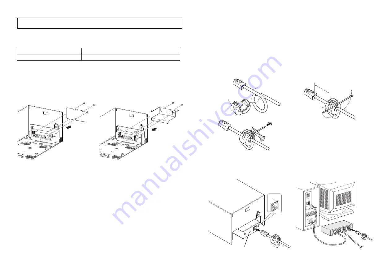
(2) Affix the ferrite core onto the Ethernet cable as shown in the illustration.
(3) Pass the fastener through the ferrite core.
(4) Loop the fastener around the cable and lock it. Use scissors to cut off any excess.
(5) Connect the Ethernet cable to the connector on the interface board. Then, connect
the other end of the cable to your computer.
(6) You can check the settngs of the interface board and the IP address by running a
self-print.
This is an optional interface board for the following printers.
Use the following procedure to install the interface board.
Interface Board
Applicable printer
IFBD-BE05 ........ Ethernet
FVP10 Series
1. Replacing the interface board
(1) Make sure that the AC adapter’s power cable plug is not connected to the outlet.
(2) Remove the three screws.
(3) Remove the blind plate in the direction of the arrow.
(4) Slide the new interface board into the printer until it is firmly seated.
Note: Insert the interface board so that it connects with the connector.
(5) Secure the interface board using the three screws that you removed in step 2.
(6) Once the interface board has been connected, perform a self-print test before con-
necting the Ethernet cable. Also, make sure that the printer recognizes the inter-
face board. When recognized: Prints “Interface: 100/10 BASE”.
2. Initializing Settings
Set the push switches as described below to initialize the setting information. Push
the switches for one to five seconds while running under normal operating mode. The
green and red LEDs will flash with a regular pattern.
After that, push the switches once again in that state to turn OFF both of the red and
green LEDS. This will return the settings of the interface board to their default, or
ex-factory, settings. After the interface board has been initialized, the printer will au-
tomatically reboot itself.
3. LED Display
Green (100M):
Lights when the port is operating at 100 Mbps.
Red (Link/Activity):
Lights when a link of the port and connected device is es-
tablished, and both are ready to communicate.
Installing the Interface Board
80876440 IFBD-BE05
© Copyright 2010 Star Micronics Co.,
Ltd.
DC
24V
SW
100/10BASE
DC
24V
Ferrite core
Ethernet cable
Fastener
100
/10
BA
SE
SW
3.5 cm
(maximum)
Push switch
LED


