background image

6

LEVELING UNIT

This griddle is supplied with (4) feet which must be
screwed into the legs attached to the body. Level unit
by adjusting the (4) feet which have an adjustment of
1-3/4" (43.75mm) for accurate and perfect lineup with
other units.

CAUTION

DO NOT INSTALL WITHOUT ATTACHING
FEET - DO NOT REMOVE FEET.

GAS PIPING

Gas piping shall be of such size and so installed as to
provide a supply of gas sufficient to meet the full gas
input of the appliance. If the appliance is to be connected
to existing piping, it shall be checked to determine if it
has adequate capacity. Joint compound shall be used
sparingly and only on the male threads of the pipe
joints. Such compounds shall be resistant to the action
of LP gases. To connect to gas supply, attach pipe
nipple provided with unit, attach pressure regulator to
nipple, and gas supply to regulator. WARNING: Any
loose dirt or metal particles which are allowed to
enter the gas lines on this appliance will damage the
valve and affect its operation. When installing this
appliance, all pipe and fittings must be free from loose
dirt.

GAS PRESSURE REGULATOR

A convertible pressure regulator is provided with each
griddle. It should be connected to the inlet pipe at the
rear of the unit. The gas supply line is then connected
to it. It is shipped set for 6" (15.24cm) water column
manifold pressure for use with natural gas.

MANUAL SHUT-OFF VALVE

A manual shut-off valve should be installed upstream
from the union and within 6 feet (1.829m) of this
appliance.

PROPANE GAS

This griddle is equipped with fixed orifice hoods and is
shipped from the factory for use on natural gas. To
convert to propane gas, install the #55* burner orifice
hoods, located in the grease drawer, as follows:
1. Remove front panel by removing screws located

on the front and the bottom.

2. Remove firewall shield and screws from burner

bracket.

3. Remove burner(s) from orifice of hood(s). This is

accomplished by lifting up on the rear of the
burner(s) and sliding the burner(s) off of the hood(s).

4. Remove natural gas orifice hood(s) and install the

propane hood(s) furnished.

5. Reinstall burner(s).

Note:  Steps 2, 3 and 4 apply to MZ models only

* TCHSZ & TSPZ Series (w/safety pilots) use a #41
drill orifice for natural gas and a #52 drill orifice for
propane gas.

6. Reinstall front panel.
7. Remove the slotted, or hex-threaded, plug from

the pressure regulator.  Invert the plug and re-
install.  The letters "LP" should now be visible on
the plug.  The regulator is now set for 10" (25.4cm)
water column.

8. Set manifold pressure to 10" (25.4cm) water

column. A 1/8" pipe plug on the supply pipe can be
removed for attaching a pressure gauge.

CONNECTING GAS SUPPLY LINE

The gas inlet of the griddle is sealed at the factory to
prevent entry of dirt. Do not remove this seal until the
actual connection is made to the gas supply line.

CHECKING FOR GAS LEAKS

Soap and water solution or other material acceptable
for the purpose shall be used in locating gas leakage.
Matches, candle flame, or other sources of ignition
shall not be used for this purpose. Check entire piping
system for leaks.

LIGHTING INSTRUCTIONS

When griddle is first lit, it will smoke until the
preservation oils and impurities are burned off.
1. Turn off main valve to unit and wait 5 minutes to

clear gas.

2. Turn off all knobs and pilot valves.
3. Turn on main valve and light all pilots.
4. Turn burner knobs to desired setting.
5. To turn burners off, turn knobs off.

NOTE: The griddles are equipped with standing pilots
and should be lit immediately after the gas is turned on.

Summary of Contents for 8G-615MZ

Page 1: ...x 314 781 3636 Installation and Operating Instructions STAR MAX GAS GRIDDLE MODELS 8G 615MZ 8G 624MZ 8G 636MZ 8G 615TZ 8G 624TZ 8G 636TZ 8G 648MZ 8G 624MZS 8G 636MZS 8G 648TZ 8G 624TSPZ 8G 636TSPZ 8G 648TSPZ CHROME MAX GAS GRIDDLE MODELS 8G 624TCHSZ 8G 636TCHSZ 8G 648TCHSZ 2M Z6394 Rev A 2 16 04 ...

Page 2: ... Controls 80 000 BTU 996 sq in 6426 sq cm Grid Area 3 4 1 9 cm Plate Thickness Approximate Weight Installed 330 Lb 144 7 kg Shipping 350 Lb 158 8 kg Dimensions 48 Width 27 3 4 Depth 13 1 2 Height 122 cm Width 70 5 cm Depth 34 3 cm Height 8G 615TZ Type Thermostat Control 1 Control 20 000 BTU 304 sq in 1961 sq cm Grid Area 3 4 1 9 cm Plate Thickness Approximate Weight Installed 83 Lb 37 6 kg Shippin...

Page 3: ...ea 3 4 1 9 cm Plate Thickness Approximate Weight Installed 330 Lb 144 7 kg Shipping 350 Lb 158 8 kg Dimensions 48 Width 27 3 4 Depth 13 1 2 Height 122 cm Width 70 5 cm Depth 34 3 cm Height 8G 624TCHSZ Type Thermostat Safety Pilot Control with Chrome Plate 2 Controls 56 6000 BTU 498 sq in 3213 sq cm Grid Area 3 4 1 9 cm Plate Thickness Approximate Weight Installed 165 Lb 74 8 kg Shipping 175 Lb 79 ...

Page 4: ...tions and product design without notice Such revisions do not entitle the buyer to corre sponding changes improvements additions or replacements for previously purchased equipment MAINTENANCE AND REPAIRS Contact your local authorized service agent for service or required maintenance Refer to the authorized service center listing provided with the unit The Star Service Help Desk 1 800 807 9054 is a...

Page 5: ...m at test pressures in excess of 1 2 PSIG 3 45KPA This appliance and its pressure regulator must be isolated from the gas supply piping system by closing its individual manual shutoff valve during any pressure testing of the gas supply piping system at test pressures equal to or less than 1 2 PSIG 3 45KPA For your protection we recommend a qualified installingagencyinstallthisappliance Theyshould ...

Page 6: ... burnerorifice hoods located in the grease drawer as follows 1 Remove front panel by removing screws located on the front and the bottom 2 Remove firewall shield and screws from burner bracket 3 Remove burner s from orifice of hood s This is accomplished by lifting up on the rear of the burner s andslidingtheburner s offofthehood s 4 Remove natural gas orifice hood s and install the propane hood s...

Page 7: ...tips disappearandahardblueflameisobtained Repeat for all burners BURNER OPERATION MODELS 615MZ 624MZ 636MZ and 648MZ ONLY To ignite burners turn burner valve knob to HI position Each burner is controlled by an individual high low on off valve An infinite number of temperatures may be obtained by turning the burner valve knob to any position between high and low OVERNIGHTSHUTDOWN Turn knobs to the ...

Page 8: ...nated cleaner such as Bon Ami may be used to wipe surface clean followed by wiping with clean wet cloth 3 Follow steps 2 and 3 from Griddle Care Non Chromium Surfaces CAUTION 1 Neverusepumice griddlestones orabrasiveson the surface 2 Neverstrikegriddlesurfacewithsharpinstrument or spatula edge 3 Never use steel wool 4 Never use commercial liquid grill cleaner on the griddle surface 5 Abusing surfa...

Page 9: ...10 ...

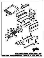
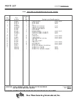
Page 10: ...LY 615MZ G3 GD0079 1 GRIDDLE PLATE ASSEMBLY 624MZ 5 G3 Y7046 1 GREASE DRAWER GRIDDLE 6 G3 Y7047 2 SLIDE DRAWER 7 2F Y7052 1 2 BURNER ASSEMBLY 615MZ 624MZ 8 G3 624044 1 MANIFOLD ASSEMBLY COMPLETE 615MZ G3 624004 1 MANIFOLD ASSEMBLY COMPLETE 624MZ 9 2P 1453 1 PLUG PIPE 10 2V 6671 1 2 VALVE PILOT 615MZ 624MZ 11 2V Y8832 1 2 VALVE MANUAL 615MZ 624MZ 12 2J Y7216 1 2 HOOD BURNER 47 NATURAL 615MZ 624MZ 1...

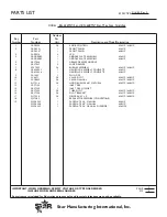
Page 11: ...LY 636MZ G3 GD0085 1 GRIDDLE PLATE ASSEMBLY 648MZ 5 G3 Y7046 1 GREASE DRAWER GRIDDLE 6 G3 Y7047 2 SLIDE DRAWER 7 2F Y7052 3 4 BURNER ASSEMBLY 636MZ 648MZ 8 G3 624045 1 MANIFOLD ASSEMBLY COMPLETE 636MZ G3 624046 1 MANIFOLD ASSEMBLY COMPLETE 648MZ 9 2P 1453 1 PLUG PIPE 10 2V 6671 3 4 VALVE PILOT 636MZ 648MZ 11 2V Y8832 3 4 VALVE MANUAL 636MZ 648MZ 12 2J Y7216 3 4 HOOD BURNER 47 NATURAL 636MZ 648MZ 1...

Reviews: