M.207
2-Channel Scratch Mixer with Effects
User Manual
Page 1: ...M 207 2 Channel Scratch Mixer with E ects User Manual...
Page 2: ...nsure reliable operation of the product and to protect it from overheating and these openings must not be blocked or covered The openings should never be blocked by placing the product on a bed sofa r...
Page 3: ...9 4 2 1 2 The Button Strip 9 4 2 1 3 The LED Strip 9 4 3 E ects 10 4 3 1 Automatic and Manual Filter 11 4 3 2 Phaser Flanger 12 4 3 3 Echo Strobe 12 4 3 4 Pan Transform 13 4 3 5 Key 13 4 3 6 Frequenc...
Page 4: ...e ects parameters sampling and automation In addition the innovative M 207 expands its e ect exibility through the new frequency based e ects sends Now you can select one or more frequency bands Lo M...
Page 5: ...ll input sources Next connect your microphone and monitor headphones located in the Front Panel Figure 3 2 Finally connect the stereo outputs to the power ampli er s and or audio receivers such as tap...
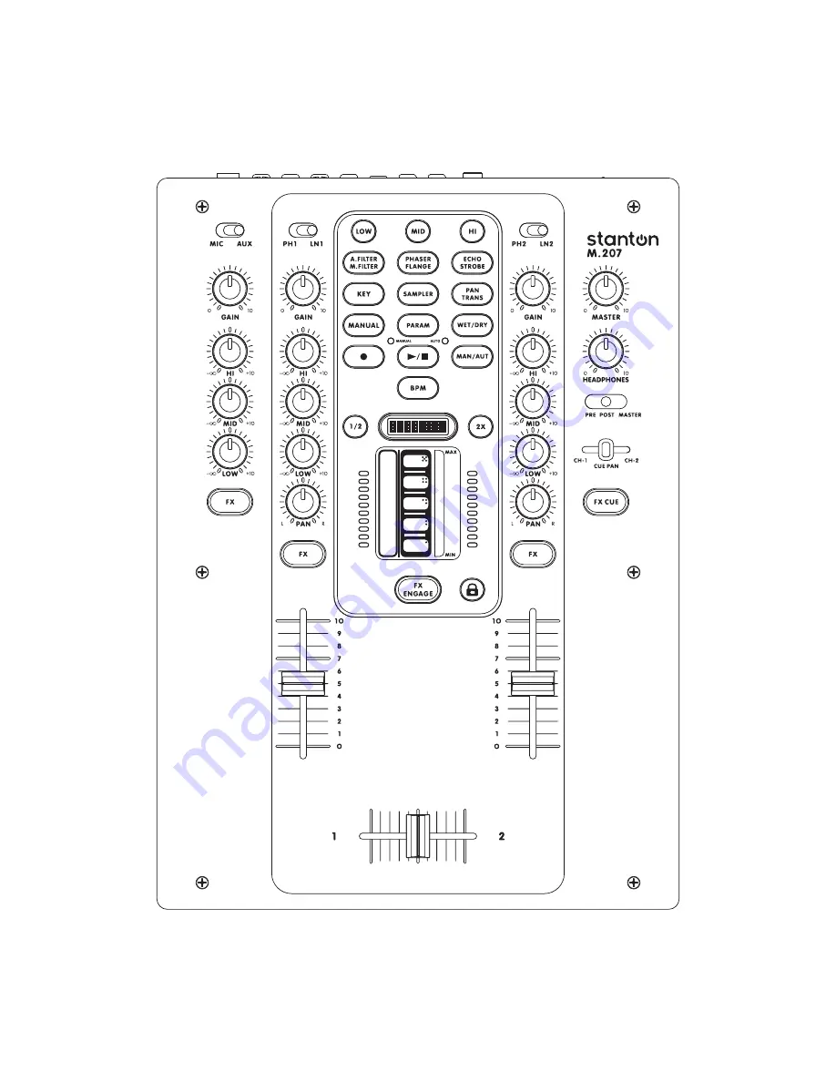
Page 6: ...M 207 Description 3 M 207 Description 3 1 Top Panel Figure 3 1 3 Figure 3 1...
Page 7: ...So if the Crossfader is centered both channels will be sent to the outputs so you are able to fade mix or cut scratch between channels 1 2 signals 13 Frequency FX LOW MID HI The LOW MID and HI button...
Page 8: ...a allows you to control FX parameters and data entry by simply touching one of its 2 distinct areas one is a slider and the other a row of buttons Its LED indicators not only display the current state...
Page 9: ...om of the fader is the loudest point and the top cuts audio completely 4 Channel Reverse CHAN REVERSE Switches which Channel Fader controls Input 1 and 2 If the Channel Reverse switch is in engaged ON...
Page 10: ...or practicing or team routines 6 REC The record output is not a ected by the Master volume control It can be used to record to a computer CD MD tape recorder even while the master volume is turned dow...
Page 11: ...d Reversing a Channel Fader Curve 1 Use the Fader Curve FDR CURVE knob to select between a LONG MID or SHARP fade for the corresponding Channel Fader 2 To reverse the Channel Fader direction set the F...
Page 12: ...ed 0 is always the bottom and 100 is always the top Touching a speci c point on the slider results in a speci c value being generated 4 2 1 2 The Button Strip The Button Strip B is a vertically aligne...
Page 13: ...e button will blink to indicate that the lower e ect is engaged Figure 4 4 Figure 4 4 An FX button will light up red to let you know that it is active Having the FX button engaged on a channel will al...
Page 14: ...available under the manual lters the Manual Filter Hi Pass Filter and Low Pass Filter To scroll between them hold down the M FILTER button Figure 4 8 M Filter Figure 4 8 Man tr The Manual Filter is a...
Page 15: ...ng to a quarter of a beat long The PARAM button controls the amount of signal fed into the echo A small PARAM value results in a shorter and quieter echo longer PARAM values produce longer and louder...
Page 16: ...active BPM and the beat division selected on the FXGlide Button Strip The PARAM button changes the gap length with a high value giving long gaps and short stabs of audio and a low value giving you sho...
Page 17: ...me way that the M Filter e ects do HI is a High Pass Filter and PARAM controls the roll o point MID is a notch lter and PARAM controls the notch frequency LOW is a Low Pass Filter where PARAM controls...
Page 18: ...ust have the CHANNEL FX ON but the FX Engage button OFF 2 Select the frequency range you want to send the e ect to Figure 4 18 In this case we are sending it to the Mid range frequencies When you rst...
Page 19: ...en your nger rst touches the strip you will see the LCD display say AUTOREC to indicate that automation is being recorded Any time you lift your nger o the slider strip the FXGlide value will go to 0...
Page 20: ...e you are doing your recording Remember that any time you lift your nger o the slider strip the FXGlide value will go to 0 To make a smooth sounding pattern keep your nger on the slider strip until th...
Page 21: ...T button Figure 4 25 to toggle the LEDs above the PLAY STOP button between AUTO and MANUAL Make sure that the green MANUAL LED is lit Figure 4 26 Press the SAMPLER button Figure 4 26 1 To arm recordin...
Page 22: ...t Figure 4 28 The selected beat division will ash brie y on the LCD screen You are now ready to create a sample Press any of the 5 button areas and a sample will record to that particular slot Conside...
Page 23: ...ARAM button 2 Figure 4 31 You can use the top 2 or bottom 2 buttons in the FXGlide Button Strip to select playback modes The top 2 buttons put the sampler into LOOP mode and the bottom 2 put it into O...
Page 24: ...ot solve the issue check that the FX button is pressed and that you have selected a speci c e ect by pressing on its related button The Channel Fader does not react as expected Please check the Channe...
Page 25: ...elays However if Tech Support determines that a repair is needed please call us at 1 954 949 9600 to obtain a Return Authorization Number RA PRIOR to shipping your product to us Warranty Service outsi...
Page 26: ...on dealer in the country where the purchaser is located or the country in which the merchandise was received Any returns to a non authorized dealer or to an authorized Stanton dealer not in the same c...
Page 27: ...than 0 1 1 kHz A WEIGHTED Mic Less than 0 1 1 kHz A WEIGHTED 8 MAXIMUM INPUT 1 kHz THD 1 EQ FLAT UNITY GAIN FX OFF LOAD 100K ohm Line Aux More than 14 dBV Phono More than 26 dBV Mic More than 26 dBV 9...
Page 28: ...egistered trademarks of the Stanton Group All other trademarks are property of their respective owners who are in no way a liated with Stanton DJ or SC System products All information included in the...