background image

Connecting the M.203

2.

Connecting the M.203

Before starting to connect the M.203, please read the Important Safety Instructions page and the following guidelines:

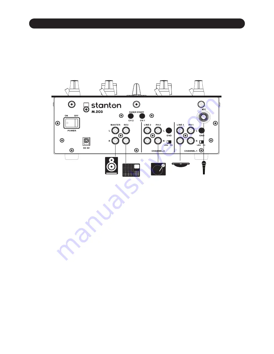
Study this setup diagram (Figure 2.1). Make sure all faders are at "zero,” the Master knob is turned all the way counterclockwise,

and all devices are Off. 

2

First, connect all input sources. Next, connect your microphone and headphones (located in the Front Panel, Figure 3.2). Finally,

connect the stereo outputs to the power amplifier(s) and/or audio receivers such as tape decks. Plug your mixer and other devices

into AC power. Now, switch everything on in the following order; audio input sources such as turntables or CD players first, then

your mixer, and finally any amplifiers. 

When turning Off, always reverse this operation by turning Off amplifiers, then your mixer, and lastly any input devices.

Figure 2.1

Summary of Contents for M.203

Page 1: ...M 203 2 Channel Scratch Mixer User Manual...

Page 2: ...nsure reliable operation of the product and to protect it from overheating and these openings must not be blocked or covered The openings should never be blocked by placing the product on a bed sofa r...

Page 3: ...Description 3 3 1 Top Panel 3 3 2 Front Panel 5 3 3 Rear Panel 6 4 Using the M 203 7 4 1 Front Panel Controls 7 4 1 1 Fader Start 7 4 1 2 Selecting and Reversing the Crossfader Curve 7 4 1 3 Selecting...

Page 4: ...gned by working DJs with the goal of creating an approachable layout for aspiring DJs and a familiar look and feel that experience pros will appreciate FEATURES INCLUDE Rugged all metal inner chassis...

Page 5: ...ct all input sources Next connect your microphone and headphones located in the Front Panel Figure 3 2 Finally connect the stereo outputs to the power ampli er s and or audio receivers such as tape de...

Page 6: ...M 203 Description 3 M 203 Description 3 1 Top Panel Figure 3 1 3 Figure 3 1...

Page 7: ...re channel fader 7 or Master 12 volume depending on what is selected on the Meter Select switch 8 10 Fader Curve Switch This switch selects between a LONG or SHARP fade for the crossfader 11 Crosssfad...

Page 8: ...M 203 Description Front Panel 3 2 M 203 Description Front Panel Figure 3 2 5 Figure 3 2 1 Headphone Output Standard 1 4 headphone output connector...

Page 9: ...ector 6 Line Phono Inputs Unbalanced RCA jacks for connecting stereo audio from sources such as Turntables CD players Hi Fi VCRs cassette decks DAT machines laser discs even synthesizers or other mixi...

Page 10: ...ON position this function allows the fader to activate or return to the preset Cue Point on your compatible CD Player Now let s customize the Crossfader curve 4 1 2 Selecting the Crossfader Curve 1 U...

Page 11: ...tables Line for CD players etc that the Turn down the Input Gain Control and check EQ settings The Fader Start feature does not work Are you using a CD player that includes that feature Are you proper...

Page 12: ...elays However if Tech Support determines that a repair is needed please call us at 1 954 949 9600 to obtain a Return Authorization Number RA PRIOR to shipping your product to us Warranty Service outsi...

Page 13: ...on dealer in the country where the purchaser is located or the country in which the merchandise was received Any returns to a non authorized dealer or to an authorized Stanton dealer not in the same c...

Page 14: ...n 0 1 1 kHz A WEIGHTED 8 MAXIMUM INPUT 1 kHz THD 1 EQ FLAT UNITY GAIN FX OFF LOAD 100K ohm Line More than 14 dBV Phono More than 26 dBV Mic More than 26 dBV 9 MAXIMUM OUTPUT 1 kHz THD 1 EQ FLAT MAXIMU...

Page 15: ...tered trademarks of the Stanton Group All other trademarks are property of their respective owners who are in no way a liated with Stanton DJ or SC System products All information included in the User...

Reviews: