9
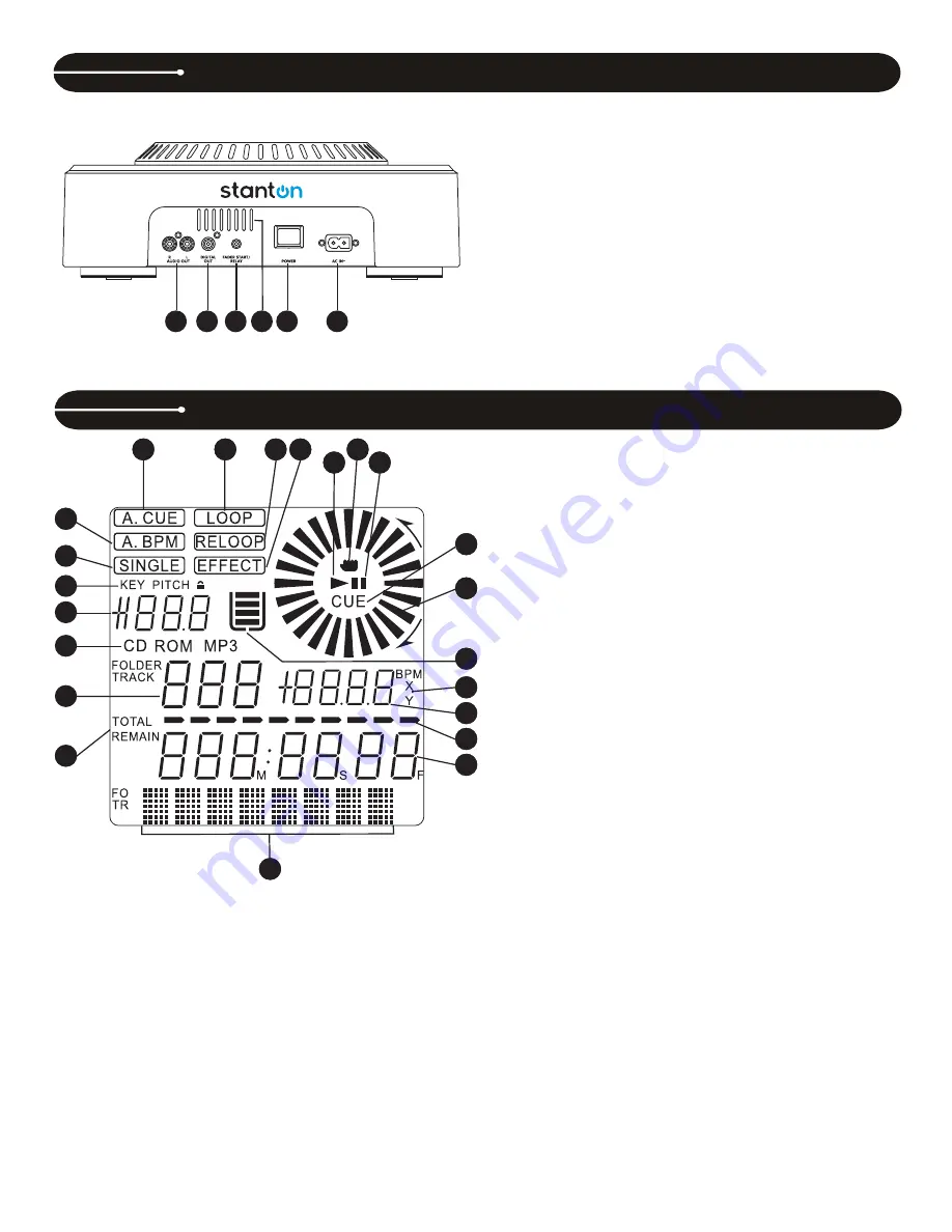
36. AUDIO OUT
– This analog output signal requires a pair of RCA
cables (left and right) to be connected to a line level input.
37. DIGITAL OUT
– This digital output signal requires one S/PDIF
(75Ohm, coaxial) cable to be connected to a S/PDIF input on your
mixer or computer.
38. FADER
START/
RELAY
– This connection allows two CD players to
be linked for relay play. This can also be connected to a mixing board
that supports automatic fader start.
39. VENT
SLITS
– These openings are used for the proper ventilation of
the unit. In order to prevent overheating and to ensure proper
operation, do not cover or block these slits.
40. POWER
BUTTON
– Turns the unit on and off.
41. AC
IN
– Plug in the power supply cable here. The plug can only be
inserted in one direction, so do not force it.
42. TRACK
– Indicates the current track selected or being played.
43. CD/MP3
– Indicates whether the current disc is a standard audio disc
or an MP3 disc.
44. PITCH
VALUE
– Shows the percentage of the pitch slider.
45. LOCK
– Shows when Pitch Lock and/or Key Lock are active.
46. SINGLE
– Controlled by the CTN/SGL button, this indicates when the
unit is set to play just one track at a time. When this is not illuminated,
the CD will play continuously through all tracks.
47. A.BPM
– Indicates when Auto BPM is active. To activate, press and
hold the TAP button.
48. A.CUE
– Indicates when Auto Cue is active. To activate Auto Cue,
press and hold the SGL/CTN button.
49. LOOP
– Indicates when the CD is in loop mode.
50. RELOOP
– Indicates when there is a previously set loop, and that the
loop is ready to be played again.
51. EFFECT
– Indicates when an effect is active.
52. PLAY
– Indicates when the unit is currently playing a CD.
53. HAND
– Indicates when the touch sensitive surface of the jog wheel
is active.
54. PAUSE
– Indicates the unit is in CUE or PAUSE mode.
55. CUE
– Indicates the unit is at a cue point and is ready to play.
56. WHEEL INDICATOR
– This is a visual representation of a vinyl
marker, which is traditionally used to mark the location of a certain
sound or cue point on a vinyl record. Here, it indicates the play
position, rotates during playback in either direction, and stops during
cue or pause mode. It also indicates the speed of the forward and
reverse search operation.
57. ANTI SHOCK AND BUFFER INDICATOR
– Indicates the current
status of the buffer memory. This is represented on the display by a
bucket being filled or emptied. The bucket itself represents the instant
start function (which works by buffer memory). If the bucket is
flashing, the instant start is not available. Each bar within the bucket
represents 2 seconds of anti shock protection. There is up to 10
seconds of anti shock protection available. It is recommended to let
the bucket fill up before using the jog wheel in vinyl mode.
58. X/Y/BPM
– Indicates whether PARAMETER (#59) is displaying the
BPM or effect parameters.
59. PARAMETER
– Shows the current BPM count, or tempo of the music.
Also shows the effects TIME and RATIO parameters while they are
being adjusted.
60. TIME BAR
– Shows a proportionate visual representation of the time
remaining or time elapsed.
61. TIME DISPLAY
– Displays the time of track(s) currently selected in
increments of Minutes, Seconds, and Frames.
62. TEXT
– The text portion of the display (the bottom row) is mainly
used to display MP3 file names or CD text information. It is also used
to display various messages, such as effects parameter settings and
so on. See operating instructions for further explanation.
63. ELAPSED / TOTAL/ REMAIN
– Indicates whether the time shown on
the display refers to total remaining time or track remaining time. If
either of these are not illuminated, this indicates elapsed track time.
CONTROL OVERVIEW C.324
LCD DISPLAY C.324
41
40
38 39
37
36
37
46
42
47
43
44
45
37
48
37
49
37
50
37
51
37
52
37
54
37
55
37
56
37
57
37
53
37
58
37
59
37
60
37
61
37
62
37
63
Summary of Contents for C.324
Page 1: ...DIGIPAK PRO V4 USER MANUAL...


