11
Alignment
TX Deviation Adjustment
Turn the Antenna switch to the “TX Alignment” side.
Confirm that the solder jumper
JP1001
is removed.
Set the AF Signal Generator output to 200 mVrms at 1
kHz.
Set the channel to CH16.
With the
PTT
switch pressed, adjust
VR1001
so that
the maximum deviation is 4.4 kHz ± 0.1 kHz.
Release the
PTT
switch.
Solder the jumper
JP1001
.
Squelch Level Adjustment
Turn the Antenna switch to the “RX Alignment” side.
Set the channel to CH16.
Set the RF Signal Generator output to 156.800 MHz,
at a level of +0 dB
μ
(HX280S) or +3 dB
μ
(HX280E),
±3.0 kHz deviation with a 1 kHz audio tone.
Connect the DC voltmeter to
TP1018
, adjust
VR1005
so that DC voltmeter reading is 0.2 V ± 0.02 V (HX280S)
or 0.45 V ± 0.02 V (HX280E).
Software Alignment/Confirmation Mode
Overview of Software Alignment Mode
The “Software Alignment Mode” has been build in
the microprocessor in order to adjust and confirm the
performance of transceiver.
The purpose is to adjust transceiver simply and to con-
firm the performance of transceiver smoothly.
Starting Software Alignment Mode
Set the channel to CH16, then turn the
VOL
knob
counter clockwise to turn off the radio.
Turn the Antenna switch to the “RX Alignment” side.
Turn the
VOL
knob clockwise to
turn on the radio while press and
holding the [
PRESET
] keys. The
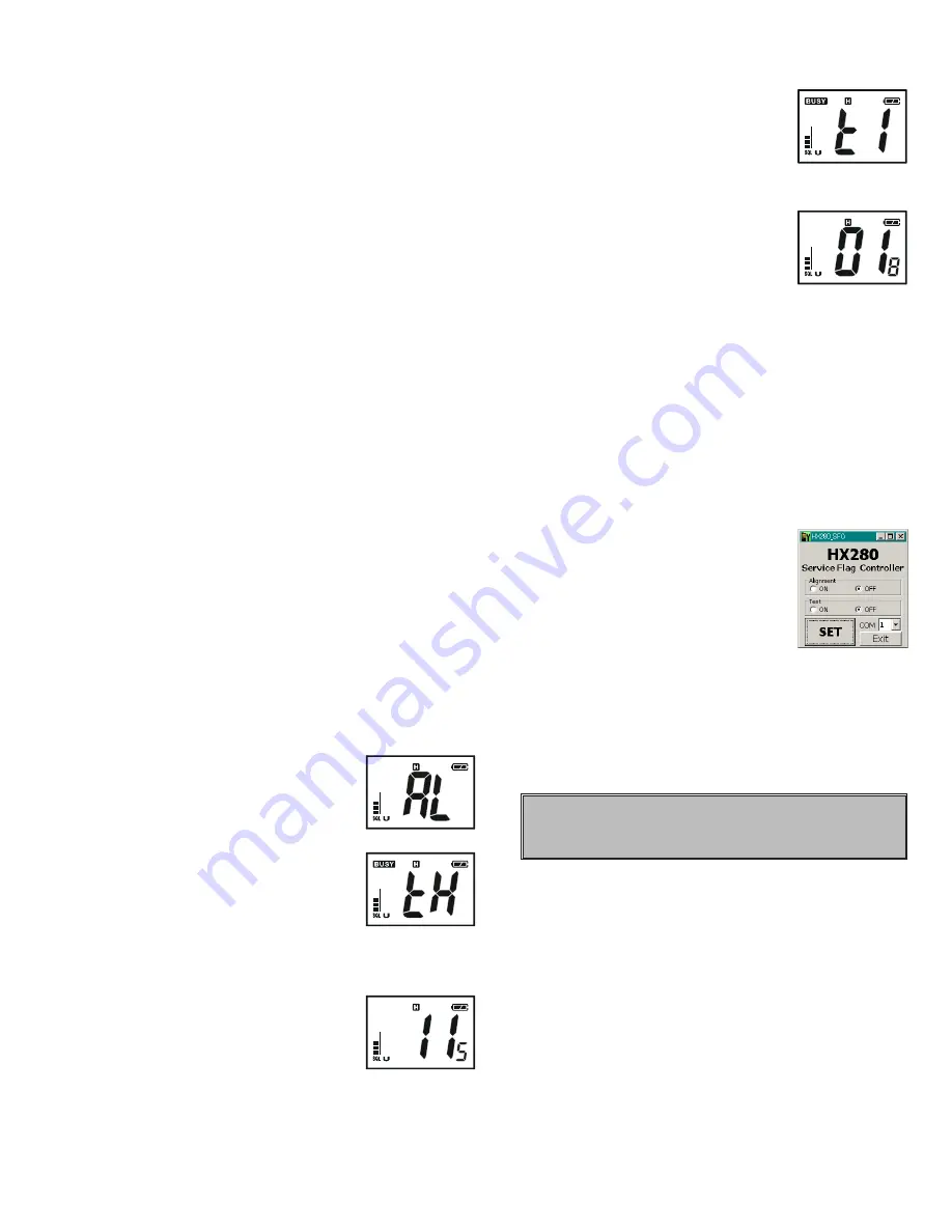
LCD will be shown the Alignment
mode “
AL
AL
AL
AL
AL
”.
Press the [
SCAN
] key. Then the LCD
will be shown the Alignment Item
(1st Item is Threshold “
tH
tH
tH
tH
tH
”).
Set the RF Signal Generator output
to 156.800 MHz, at a level of –8 dB
μ
(HX280S) or
–6 dB
μ
(HX280E), ±3.0 kHz deviation with a 1 kHz
audio tone.
Press the [
PRESET
] key to record a
threshold level.
Press the [
MEM
] key to save the new
setting.
Press the [
SCAN
] key to recall the
Alignment Item “
tI
tI
tI
tI
tI
(TIGHT)”.
Set the RF Signal Generator output
to 156.800 MHz, at a level of +0 dB
μ
(HX280S) or +3 dB
μ
(HX280E), ±3.0 kHz deviation
with a 1 kHz audio tone.
Press the [
PRESET
] key to record a
tight level.
Press the [
MEM
] key to save the new
setting.
This completes the Software Alignment Mode. To save
all settings and exit, press and hold the [
16/9
] key for one
second. Then turn off the transceiver.
After Alignment
Execute the HX280 Service Flag Controller Program
again.
Select the COM port number which is connected to
the HX280 Alignment Jig.
Press and hold in the [
PRESET
] key while turning
the transceiver on to enter the Alignment Mode.
Select “Alignment OFF” Radio But-
ton of HX280 Service Flag Control-
ler Program.
Click the left mouse button on the
[
SET
] button of the HX280 Service
Flag Controller Program.
Turn off the transceiver.
Assemble the transceiver while being carefully so that
Rubber Packing does not protrude from a Front Case.
Important Note: To ensure the radio is water proof,
make sure the gasket is installed on the chassis cor-
rectly and is not pinched when inserted into the front
case.
NOTICE
Do not touch the Alignment Item “
dC
dC
dC
dC
dC
”.
Summary of Contents for HX280E
Page 1: ...1 SERVICE MANUAL VHF FM Marine Transceiver HX280S E EM038N90A HX280S HX280E ...
Page 5: ...5 Block Diagram ...
Page 6: ...6 Note ...
Page 12: ...12 Note ...
Page 14: ...14 MAIN Unit Note ...
Page 24: ...24 Note MAIN Unit ...
Page 28: ...28 Note ...
Page 29: ...HX280S E Main Unit Circuit Diagram 1 2 3 5 6 7 4 8 ...
Page 30: ...HX280S E Main Unit Circuit Diagram 1 2 3 5 6 7 4 8 ...
Page 31: ...HX280S E Main Unit Circuit Diagram 1 2 3 5 6 7 4 8 ...
Page 32: ...HX280S E Main Unit Circuit Diagram 1 2 3 5 6 7 4 8 ...
Page 33: ...HX280S E Main Unit Circuit Diagram 1 2 3 5 6 7 4 8 ...
Page 34: ...HX280S E Main Unit Circuit Diagram 1 2 3 5 6 7 4 8 ...
Page 35: ...HX280S E Main Unit Circuit Diagram 1 2 3 5 6 7 4 8 ...
Page 36: ...HX280S E Main Unit Circuit Diagram 1 2 3 5 6 7 4 8 ...
Page 37: ...HX280S E Main Unit Side A Parts Layout 1 2 ...
Page 38: ...HX280S E Main Unit Side A Parts Layout 1 2 ...
Page 39: ...HX280S E Main Unit Side B Parts Layout 1 2 ...
Page 40: ...HX280S E Main Unit Side B Parts Layout 1 2 ...
Page 41: ...29 Note ...


