

Part # Part Name
Qty
1
Base Frame
2
2
Upright
2
3
Crossing Barre
1
4
Quick Release
2
5
Endcap (38mm)
4
6
Spring Pin
2
7
Bushing
2
8
Round Plug
2
9
Bolt, Button Head (M8x1.25x15mm)
2
10
Button Pin
2
11
Caution Label
1
12
Caution Decal
1
13
Studio Barre DVD
1
14
Carry Bag
1
Products shipped to the manufacturer must be in the original shipping carton with freight prepaid. All expenses for repairing or replacing
the product, including the cost of shipping it back to the original purchaser, will be covered by the manufacturer. This warranty gives you
specific legal rights, and you may have other rights which vary from state to state.
If the product should, for any reason, become defective for a period of 90 days on the parts and one year on the frame from the
date of the purchase, the manufacturer will replace the product once it is returned to the manufacturer. This warranty does not
apply to any damage caused by accident, return transit, improper assembly, alteration, abuse, or misuse. There are no other
warranties other than those expressly set forth herein.
This product is warranted to be free from defects in material and workmanship and to be in perfect working order at the time of
purchase. This warranty applies to personal, family or household use. This warranty does not apply to use in athletic clubs, health
clubs, spas, gymnasiums, exercise facilities, and other public or semipublic facilities.
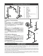
Product Parts Drawing and Parts List
LIMITED WARRANTY
Assembly of The Studio Barre
Adjustment
Holes
B.
A.
STEP 1
Refer to illustration A. Loosen the
QUICK RELEASE(4).
Insert
the
BASE FRAME(1)
into the
UPRIGHT(2)
until the
BUTTON
PIN(10)
gets into the hole in the bottom end of the
UPRIGHT(2).
Tighten the
QUICK RELEASE(4)
to lock the
BASE FRAME(1)
in
position securely. Repeat on other side.
STEP 2
Refer to illustration B. Pull the
SPRING PIN(6)
then insert an
UPRIGHT(2)
through the
CROSSING BARRE(3).
Release the
SPRING PIN(6)
so it catches in one of the adjustment holes and
locks the
UPRIGHT(2)
in place. Tighten the
SPRING PIN(6)
to
lock the
UPRIGHT(2)
in place securely. Repeat on other side
and position the
CROSSING BARRE(3)
at the same height as
other side.
To adjust the height of the
CROSSING BARRE(3),
turn the
SPRING PINS(6)
counter clockwise until the knob portion can
be pulled. Pull both
SPRING PINS(6)
at the same time and slide
the
CROSSING BARRE(3)
up or down to adjust. Release the
SPRING PINS(6)
to lock the
CROSSING BARRE(3)
in the desired
adjustment holes. Rotate the
SPRING PINS(6)
clockwise to lock
the
CROSSING BARRE(3)
securely.
NOTE:
Always make sure that the
CROSSING BARRE(3)
is
adjusted at the same height.
Crossing Barre Adjustment


