10
Assembly Manual
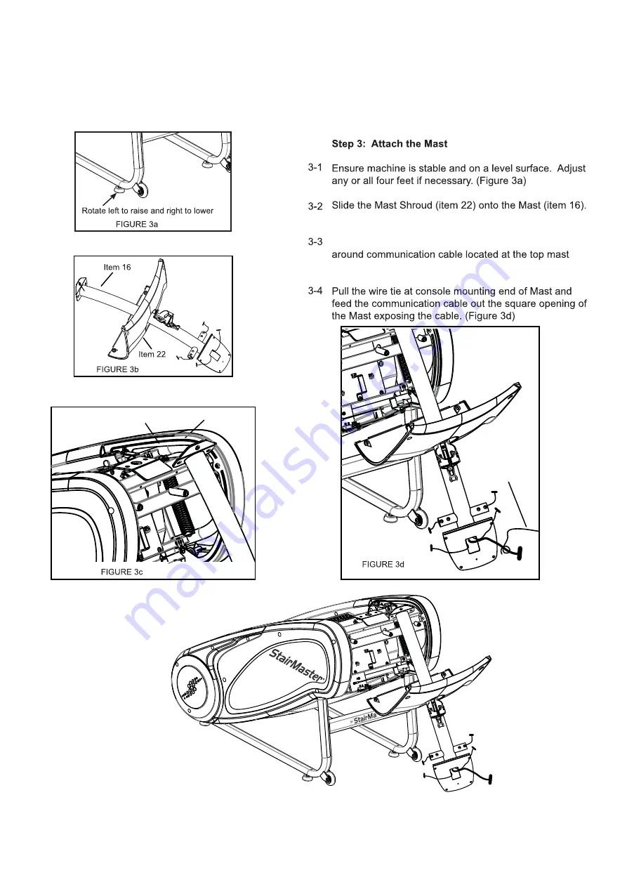
Assembly
_____________________________________________________
(Figure 3b)
Using the wire tie within the Mast, wrap the wire tie
mounting area on the machine. (Figure 3c)
Console Cable
Wire Tie
Page 1: ...StepMill 3 Assembly Manual 030 0024B...
Page 2: ...l SM3 Dimensions LWH 46 x 29 x 73 117 cm x 74 cm x 185 cm Unit Weight 223 lbs 101 kg Shipping Package Weight 298 lbs 135 kg Workout Area 67 W x 84 L 170 cm x 213 cm Max User Weight 275 lbs 125 kg Regu...
Page 3: ...tructions ________________________________________________________________________________ T V X N I Y Z N K Y Z N K R V N K N N Y N N N N d N T N R G dN N N f N N N N j G N f N f N X f N R N f R dN N...
Page 4: ...ined regularly for damage and wear e g chains steps Please replace defective components immediately and keep the equipment out of use until repair Warning In uries to health may result from incorrect...
Page 5: ...P N 050 2198 REV B MAX USER WEIGHT CERTIFICATIONS MFG DATE VOLT AMPS CYCLES WATTS PHASE Patents Core Health Fitness LLC 4400 NE 77th Avenue Suite 300 Vancouver WA 98662 USA 1 888 678 2476 P N 050 5456...
Page 6: ...y Manual Before you Start _____________________________________________________ 6 7 8 GN N q G w N d N N Follow these basic assembly tips when putting together your machine 1 N 2 I N 3 T R N 4 N R N 5...
Page 7: ...mm Button Head Screw 3 3 723 0240 M10 x 45mm Button Head Screw 4 4 40670 1 4 20 x 3 4 Phillips Head W Lock Washer 4 5 723 0076 M6 x 15 Phillips Head Screw 7 6 21462 16mm Flat Washer 8 7 050 0049 20mm...
Page 8: ...23 0253 Hardware Card 1 1 e l o s n o C 9 2 2 0 3 2 7 5 1 1 t s a M 1 7 1 0 3 2 7 6 1 1 t e k s a G t s a M 4 2 2 0 3 2 7 7 1 18 723 0197 Handrail RH 1 1 H L l i a r d n a H 3 8 1 0 3 2 7 9 1 20 723 0...
Page 9: ...9 Assembly Manual Assembly _____________________________________________________ StepMill 3 All instructions in the manual are See Figure 1 Tools or hammer area See Figure 2...
Page 10: ...bly Manual Assembly _____________________________________________________ Figure 3b Using the wire tie within the Mast wrap the wire tie mounting area on the machine Figure 3c Console Cable Wire Tie W...
Page 11: ...11 Assembly Manual Assembly _____________________________________________________ center with mating plate on machine Figure 3e Do not Fully tighten bolts Mating Plate...
Page 12: ...ocation and use 3pcs of screw item 5 to tighten both onto the frame as shown in figure 4a 4 2 Using 2pcs of screw item 5 attach Mast Shroud item 22 to frame as shown in figure 4b Note Ensure both shro...
Page 13: ...ssembly Manual Assembly _____________________________________________________ heart rate cable Figure 5a Use caution not to pinch heart rate cables while pushing the bolts into location Tighten all bo...
Page 14: ...14 Assembly Manual Assembly _____________________________________________________ O d O I R Q dN Jd the machine Figure 6b O I f d Communication Cable QK I K J fJd K O I f d Communication Cable QK I...
Page 15: ...15 Assembly Manual Assembly _____________________________________________________...
Page 16: ...rMaster Use the space in the boxes below to write down this information To d the serial number on your machine refer to the Safety Warning Label information page CUSTOMER SERVICE Tel 1 888 678 2476 Pa...