background image

Explanation of the symbols

4

250306 / MCP60300050

2015-10-23·BA00·III·en·00

Flameproof Manual Call Points

Series MCP/PB

EN
EN
EN
EN
EN
EN
EN
EN
EN
EN
EN
EN
EN
EN
EN
EN
EN
EN
EN
EN
EN
EN
EN
EN
EN

2.2

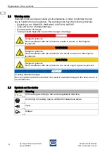
Warning notes

Warnings must be observed under all circumstances, in order to minimize the risk  

due to construction and operation. The warning notes have the following structure:

• Signalling word: DANGER, WARNING, CAUTION, NOTICE

• Type and source of danger/damage

• Consequences of danger

• Taking countermeasures to avoid the danger or damage

2.3

Symbols on the device

DANGER

Danger to persons

Non-compliance with the instruction results in severe or fatal injuries  

to persons.

WARNING

Danger to persons

Non-compliance with the instruction can result in severe or fatal injuries  

to persons.

CAUTION

Danger to persons

Non-compliance with the instruction can result in light injuries to persons.

NOTICE

Avoiding material damage

Non-compliance with the instruction can result in material damage to the device and / or 

its environment.

Symbol

Meaning

05594E00

CE marking according to the current applicable directive.

02198E00

According to marking, device certified for hazardous areas.

15649E00

Input

15648E00

Output

Summary of Contents for MCP/PB

Page 1: ...EN EN EN EN EN EN EN EN EN EN EN EN EN EN EN EN EN EN EN EN EN EN EN EN EN Operating instructions Additional languages www stahl ex com EN CS Clifford Snell Flameproof Manual Call Points Series MCP PB ...

Page 2: ...rning notes 4 2 3 Symbols on the device 4 3 Safety notes 5 3 1 Operating instructions storage 5 3 2 Safe use 5 3 3 Modifications and alterations 5 4 Function and device design 5 4 1 Function 6 5 Technical data 6 6 Transport and storage 7 7 Mounting and installation 8 7 1 Dimensions fastening dimensions 8 7 2 Mounting dismounting operating position 8 7 3 Installation 9 8 Commissioning 17 9 Operatio...

Page 3: ...m 1 4 Conformity with standards and regulations See certificates and EC Declaration of Conformity www stahl ex com The device has IECEx approval See IECEx homepage http iecex iec ch 2 Explanation of the symbols 2 1 Symbols in these operating instructions R STAHL Schaltgeräte GmbH Business Unit Lighting Signalling Nordstr 10 99427 Weimar Germany R STAHL Schaltgeräte GmbH Am Bahnhof 30 74638 Waldenb...

Page 4: ...res to avoid the danger or damage 2 3 Symbols on the device DANGER Danger to persons Non compliance with the instruction results in severe or fatal injuries to persons WARNING Danger to persons Non compliance with the instruction can result in severe or fatal injuries to persons CAUTION Danger to persons Non compliance with the instruction can result in light injuries to persons NOTICE Avoiding ma...

Page 5: ...annot be held liable for damage caused by incorrect or unauthorized use or by non compliance with these operating instructions Before installation and commissioning make sure that the device is not damaged Work on the device installation maintenance overhaul repair may only be carried out by appropriately authorized and trained personnel 3 3 Modifications and alterations 4 Function and device desi...

Page 6: ...and accessories 5 Technical data Explosion Protection Global IECEx Gas and dust IECEx BAS 08 0089X IEC 60079 0 2011 IEC 60079 1 2007 04 IEC 60079 31 2008 Ex d IIC T6 Ta 55 to 70 C Gb Ex tb IIIC T85 C Ta 55 to 70 C Db IP66 Europe ATEX Gas and dust Baseefa 08ATEX0269X EN 60079 0 2009 EN 60079 1 2007 EN 60079 31 2009 E II 2 G Ex d IIC T6 Ta 55 to 70 C Gb E II 2 D Ex tb IIIC T85 C Ta 55 to 70 C Db IP6...

Page 7: ...to IEC 60529 Cable entries 4 cable entries supplied with 3x Ex d stopping plugs and 1x dust cap Position of cable entries Connection Terminals 7 way terminal block 4 mm2 Earth connection provided as standard Accessories LED status indication optional red LED status indication up to 24 V DC Lift flap stainless steel break glass version only Duty label Metalised polyester customer to specify wording...

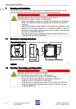
Page 8: ...l device so that explosion protection is not affected due to external influences i e pressure conditions chemical mechanical thermal and electric impact such as vibration humidity and corrosion see IEC EN 60079 14 The device must only be installed by trained qualified personnel who is familiar with the relevant standards Dimensional drawings all dimensions in mm inches subject to alterations 13954...

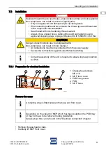
Page 9: ...eal thread with non hardening thread sealant Always close unused holes cable entries and cable glands using approved stopping plugs or plugs Observe IEC EN 60079 14 for this CAUTION Danger of electric shock due to energised parts Non compliance can result in minor injuries All connections must be disconnected from the power supply Secure the connections against unauthorized switching Correct reass...

Page 10: ...arm Make sure that the LK2 connection has been removed 16840E00 1 Cable connection from right 2 3 fixing points for PCBs 3 Breakable tabs for independent switch function 4 Terminal block 5 Connector for switch 6 LK1 LK2 and LK3 connections for special variants MCP switch can be operated normally open or normally closed to suit different systems The device can be purchased with a single or two pin ...

Page 11: ...d devices with monitoring resistors Single pin MCP switch normally closed in standby normally open in alarm 16843E00 1 Cable connection from right 2 N pin 1 3 N pin 2 4 L pin 1 5 L pin 2 16844E00 1 Cable connection from right 2 N pin 1 3 N pin 2 4 L pin 1 5 L pin 2 Standard variants with monitoring resistors are only available with switch normally closed in standby normally open in alarm Resistor ...

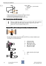
Page 12: ...ure that connector wires from switch and LED are correctly installed as per the diagram see following figure 17545E00 Active Alarm 1 Switch open In line resistor engaged 2 L 3 N There is an 820 ohm resistor which is in line with the LED When activated the LED together with the resistor will draw a current On a 24 V DC system this current is approximately 30 mA 17567E00 17568E00 C 1 1a 2 3 4 Connec...

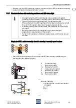
Page 13: ...as per the diagram see following figure Remove LK1 for LED activation in alarm or remove LK2 for LED activation in standby Jumper connection between terminal 1 and 2 Two pin MCP switch normally open in standby normally closed in alarm independent circuits Ensure that connector wires from switch and LED are correctly installed as per the diagram see following figure 17567E00 17568E00 C 1 1a 2 3 4 C...

Page 14: ... C 1 1a 2 2a 3 3a 4 4a Connector block Red wire for LED Black wire for LED Yellow wire for switch Yellow wire for second switch Blue wire for switch Blue wire for second switch Red wire for switch Red wire for second switch 17540E00 1 2 3 4 5 Cable connection from right N N L L 17567E00 17570E00 C 1 1a 2 2a 3 3a 4 4a Connector block Red wire for LED Black wire for LED Yellow wire for switch Yellow...

Page 15: ...able with switch normally closed in standby normally open in alarm with LED activated There is an 820 ohm resistor which is in line with the LED When activated the LED together with the resistor will draw a current On a 24 V DC system this current is approximately 30 mA In standby without the LED activated the resistance of the the PCB is 0 ohms Resistor values are to be selected by the system des...

Page 16: ...n bodies If necessary clean the connection chamber Check if the conductors have been inserted correctly Check if all screws and nuts have been tightened firmly Check if all conductors have been clamped firmly Check if all prescribed tightening torques have been observed Check whether the bayonet lock is tightened firmly Make sure that the plug pin surface is not damaged Use only in completely moun...

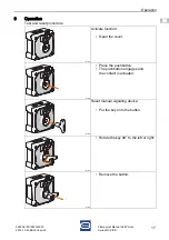
Page 17: ...proof Manual Call Points Series MCP PB 9 Operation Test and reset procedure 16581E00 Activate function Open the cover 16582E00 Press the pushbutton The pushbutton engages and the contact is actuated 16583E00 Reset manual signaling device Put the key onto the button 16584E00 Rotate the key 90 to the left or right 16585E00 Remove the button ...

Page 18: ...unauthorized work Non compliance can result in light injuries Before carrying out work on the device switch off voltage supply Work performed on the device must only be carried out by authorized and appropriately trained qualified electricians Observe the relevant national regulations in the country of use Check Measures the permissible ambient temperature If exceeding the permissible ambient temp...

Page 19: ...ter or mild non abrasive non scratching cleaning agents Do not use aggressive detergents or solvents 12 Disposal Observe national and local regulations and statutory regulation regarding disposal Separate materials when sending it for recycling Ensure environmentally friendly disposal of all components according to the statutory regulations 13 Accessories and Spare parts DANGER Explosion hazard du...

Page 20: ......

Reviews: