DEDEDEDEDEDEDEDEDEDEDEDEDEDEDEDEDEDEDEDEDEDEDEDEDE
Betriebsanleitung
Additional languages www.r-stahl.com
DE
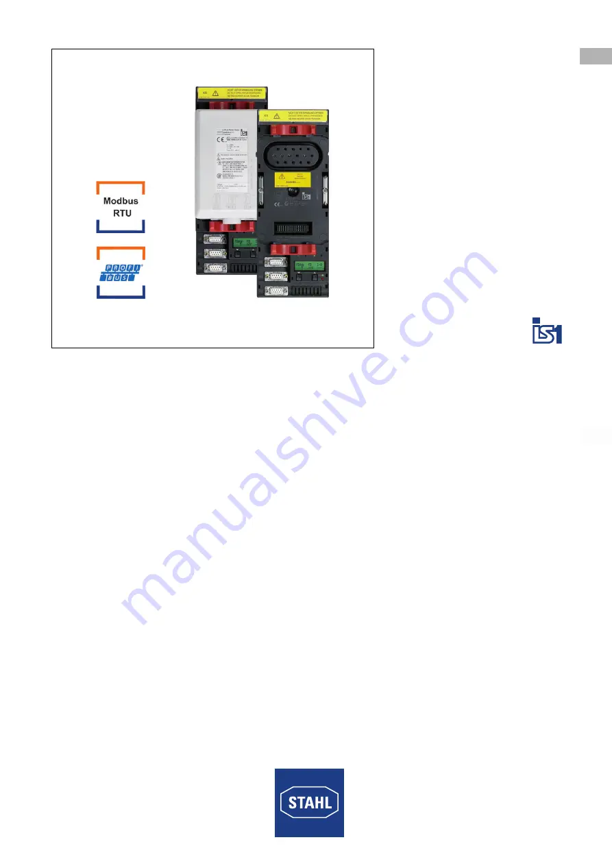
CPU & Power Modul für Zone 1 / Div. 1
Reihe 9440/22, 9490
Page 1: ...DE DE DE DE DE DE DE DE DE DE DE DE DE DE DE DE DE DE DE DE DE DE DE DE DE Betriebsanleitung Additional languages www r stahl com DE CPU Power Modul f r Zone 1 Div 1 Reihe 9440 22 9490...
Page 2: ...sonals 5 3 3 Sichere Verwendung 6 3 4 Umbauten und nderungen 7 4 Funktion und Ger teaufbau 7 4 1 Funktion 8 4 2 Ger teaufbau 8 5 Technische Daten 9 6 Projektierung 14 6 1 Hilfsenergieanschluss 15 6 2...
Page 3: ...kationsnummer 2018 08 13 BA00 III de 06 Die Originalbetriebsanleitung ist die englische Ausgabe Diese ist rechtsverbindlich in allen juristischen Angelegenheiten 1 3 Weitere Dokumente Kopplungsbeschre...
Page 4: ...en der Gefahr Ergreifen von Gegenma nahmen zum Vermeiden der Gefahr bzw des Schadens Symbol Bedeutung Tipps und Empfehlungen zum Gebrauch des Ger ts Gefahr durch explosionsf hige Atmosph re Gefahr dur...
Page 5: ...iebnahme Instandhaltung Reparatur Reinigung Fachkr fte die diese T tigkeiten ausf hren m ssen einen Kenntnisstand haben der relevante nationale Normen und Bestimmungen umfasst F r T tigkeiten in explo...
Page 6: ...t ist Stromkreise der Z ndschutzart Ex i die mit Stromkreisen anderer Z ndschutzarten betrieben wurden d rfen danach nicht mehr als Stromkreise der Z ndschutzart Ex i betrieben werden Bei Einsatz in Z...
Page 7: ...eben sind Ger t nur mit einem feuchten Tuch reinigen um elektrostatische Aufladung zu vermeiden 3 4 Umbauten und nderungen 4 Funktion und Ger teaufbau GEFAHR Explosionsgefahr durch Umbauten und nderun...
Page 8: ...t Die Stromversorgung der I O Module erfolgt ber die BusRail Die Kommunikation mit den I O Modulen erfolgt ber die Adress und Datenleitungen der BusRail Die Schnittstelle des CPU Power Moduls zum inte...
Page 9: ...ehe jeweilige Bescheinigung und Betriebsanleitung Sicherheitstechnische Daten Maximale Ausgangsspannung Uout 26 2 V f r Stromversorgung der I O Module Anschluss an eigensicheren RS485 IS Feldbus Globa...
Page 10: ...mA bei 120 V AC mit 8 I O Modulen ca 2 5 A bei 24 V DC ca 0 4 A bei 230 V AC ca 0 8 A bei 120 V AC Verlustleistung ohne I O Module 5 W 8 4 W je I O Modul ca 1 4 W ca 1 W Verpolschutz ja entf llt Unter...
Page 11: ...ms f r Analog Module 10 ms Bediener Schnittstelle Software IS1 Ger te DTM oder IS Wizard Betrieb LED gr n RUN Fehler LED rot ERR LCD Anzeige 2 x 16 Zeichen Einstellungen Busadresse Anzeigen Busadress...
Page 12: ...Hilfsenergie und System komponenten 1500 V AC zwischen Feldbus ServiceBus Schnittstelle und System komponenten 500 V AC zwischen zwei Bus Schnittstellen 500 V AC Umgebungsbedingungen Umgebungs tempera...
Page 13: ...Daten Anschluss Feldbus RS485 Sub D Buchse 9 polig ServiceBus RS485 Sub D Buchse 9 polig Hilfsenergie Modulgeh use Polyamid 6GF Brandfestigkeit UL 94 HB Schutzart IEC 60529 Module IP30 Anschl sse IP2...
Page 14: ...t dem Potentialausgleich des explosionsgef hrdeten Bereichs verbinden An den angeschlossenen Hilfsenergie Stromkreisen nur im spannungsfreien Zustand arbeiten Beim Einsatz in explosionsgef hrdeten Ber...
Page 15: ...Conduit Anschlussbelegung 6 2 Sub D Buchsen X1 X2 X3 12224E00 Anschlussbelegung 7 Transport und Lagerung Ger t nur in Originalverpackung transportieren und lagern Ger t trocken keine Betauung und ers...
Page 16: ...0 einzubauen die eine geeignete Schutzart bieten Bei Einsatz in Zone 1 2 und im sicheren Bereich ist ein Geh use mit mindestens IP54 erforderlich Bei Einsatz in Zone 21 22 ist ein Geh use mit mindeste...
Page 17: ...ihe 9440 22 9490 8 1 Ma angaben Befestigungsma e Ma zeichnungen alle Ma e in mm Zoll nderungen vorbehalten 09877E00 07762E00 9490 11 12 CPU Power Modul f r Zone 1 mit Anschluss ber Ex e Klemmen 9490 1...
Page 18: ...n kann Sachschaden verursachen Ger t ausschlie lich senkrecht montieren mit Lese Richtung der LCD Anzeige wahlweise von unten von links oder von rechts 12225E00 Sockel senkrecht auf ersten Steckplatz...
Page 19: ...schweren Verletzungen und Sachsch den f hren An den Ex e Klemmen oder am Kabelschwanz nur im spannungsfreien Zustand arbeiten 17940E00 17941E00 Rasthebel in Position II schieben Abbildung 1 Modul sen...
Page 20: ...ockels l sen Sockel senkrecht von BusRail abziehen Neuen Sockel senkrecht auf BusRail setzen siehe auch Kapitel Montage des Sockels auf BusRail Neues CPM Modul auf Sockel stecken siehe auch Kapitel Mo...
Page 21: ...ges Anzugsdrehmoment 0 5 0 6 Nm 9 1 Parametrierungen Die Parametrierung und Inbetriebnahme des CPM und der angeschlossenen I O Module erfolgt ber das Automatisierungssystem und den ServiceBus optional...
Page 22: ...e links dargestellt 12261E00 Tasten und gleichzeitig dr cken Es erscheint folgende Anzeige links dargestellt Taste oder so lange dr cken bis gew nschte Feldbusadresse eingestellt ist Bei andauerndem D...
Page 23: ...el Funktion und Ger teaufbau 10 2 2 LCD Anzeigen Informationen zu CPM anzeigen Das CPM und die Sub D Stecker k nnen w hrend des Betriebs im explosionsgef hrdeten Bereichen gefahrlos gesteckt oder gezo...
Page 24: ...system Konfiguration durch Profibus DataExch AS 2 Data Exchange mit dem Automatisierungssystem no DataExch kein Datenaustausch config para fail Konfigurations oder Parameterfehler quit DataExch kein D...
Page 25: ...hardware failure Modul meldet Hardwarefehler 2 conf unequal mod Konfigurationsfehler oder falsches Modul gesteckt 3 HW disable outp Ausg nge durch externen Schalter Anlagen Aus abgeschaltet nur bei DO...
Page 26: ...es Z hler Frequenzwertes und der Steuerbits start und reset f r Kanal 14 nur bei Input Module 12280E00 Anzeige des Z hler Frequenzwertes und der Steuerbits start und reset f r Kanal 15 nur bei Input M...
Page 27: ...och die folgenden Anzeige LCD Anzeige Anzeige Funktion 12286E00 Men zur Anzeige der HART PV Aufruf der Untermen s durch gleichzeitiges Dr cken von und 12287E00 Anzeige der konfigurierten PV Betriebsar...
Page 28: ...anden Falsches Modul gesteckt Modul tauschen Modul stecken Richtiges Modul stecken LED RUN blinkt LED ERR erloschen In Bereitschaft nach dem Einschalten aber noch ohne Datenaustausch mit dem Master Zy...
Page 29: ...der Instandhaltung des Ger ts mindestens folgende Punkte pr fen fester Sitz der untergeklemmten Leitungen Rissbildung und andere sichtbare Sch den am Ger tegeh use und oder Schutzgeh use Einhaltung d...
Page 30: ...hein in der Verpackung an die R STAHL Schaltger te GmbH senden Adresse siehe Kapitel 1 1 12 Reinigung Zur Vermeidung elektrostatischer Aufladung d rfen die Ger te in explosionsgef hrdeten Bereichen nu...
Page 31: ...EN EN EN EN EN EN EN EN EN EN EN EN EN EN EN EN EN EN EN EN EN EN EN EN EN Operating instructions Additional languages www r stahl com EN CPU Power Module for Zone 1 Div 1 Series 9440 22 9490...
Page 32: ...ation 5 3 3 Safe Use 6 3 4 Modifications and Alterations 7 4 Function and Device Design 7 4 1 Function 8 4 2 Device Design 8 5 Technical Data 9 6 Engineering 14 6 1 Auxiliary Power Connection 15 6 2 S...
Page 33: ...No 162277 9440607310 Publication Code 2018 08 13 BA00 III en 06 The original instructions are the English edition They are legally binding in all legal affairs 1 3 Further Documents Coupling descripti...
Page 34: ...E Type and source of danger damage Consequences of danger Taking countermeasures to avoid the danger or damage Symbol Meaning Tips and recommendations on the use of the device Danger due to explosive...
Page 35: ...stallation Commissioning Maintenance repair cleaning Specialists who perform these tasks must have a level of knowledge that meets applicable national standards and regulations Additional knowledge is...
Page 36: ...rotection can no longer be operated as circuits with this protection type after being operated with circuits with other types of protection If used in Zone 1 the device must be installed in an enclosu...
Page 37: ...nstructions Always clean the device with a damp cloth to avoid electrostatic charge 3 4 Modifications and Alterations 4 Function and Device Design DANGER Explosion hazard due to modifications and alte...
Page 38: ...lemented via the BusRail Communication with the I O modules is implemented via the address and data lines on the BusRail The interface of the CPU power module with the internal data bus on the BusRail...
Page 39: ...s Further information see respective certifcate and operating instructions Safety data Max output voltage Uout 26 2 V to supply the I O modules Connection to intrinsically safe RS485 IS fieldbus Globa...
Page 40: ...8 I O modules approx 2 5 A at 24 V DC approx 0 4 A at 230 V AC approx 0 8 A at 120 V AC Power dissipation without I O modules 5 W 8 4 W per I O module approx 1 4 W approx 1 W Polarity reversal protect...
Page 41: ...or Analog Modules 10 ms Operator interface Software IS1 devices DTM or IS Wizard Operation LED green RUN Fault LED red ERR LCD indication 2 x 16 characters Settings bus address Indications Bus address...
Page 42: ...pply and system components 1500 V AC between Fieldbus ServiceBus interface and system components 500 V AC between two bus interfaces 500 V AC Ambient conditions Ambient temperature 20 to 65 C Storage...
Page 43: ...ieldbus RS485 Sub D socket 9 pin ServiceBus RS485 Sub D socket 9 pin Power supply Module enclosure Polyamide 6GF Fire resistance UL 94 HB Degree of protection IEC 60529 Modules IP30 Connections IP20 M...
Page 44: ...sRail Connect the top hat rail of the BusRail to the equipotential bonding of the hazardous area Work on the connected auxiliary power electric circuits only if they are de energised If used in hazard...
Page 45: ...s of conduit Terminal assignment 6 2 Sub D Sockets X1 X2 X3 12224E00 Terminal assignment 7 Transport and Storage Transport and store the device only in the original packaging Store the device in a dry...
Page 46: ...f protection in accordance with IEC EN 60079 0 An enclosure with at least an IP54 protection rating is required for use in Zones 1 2 and in safe areas An enclosure with at least an IP64 protection rat...
Page 47: ...astening Dimensions Dimensional drawings all dimensions in mm inches Subject to alterations 09877E00 07762E00 9490 11 12 CPU power module for Zone 1 with connection by means of Ex e terminals 9490 12...
Page 48: ...lt in material damage Mount the device in vertical direction only with the reading direction of the LCD display from below left or right as desired 12225E00 Position the base vertically onto the first...
Page 49: ...can result in severe injuries and material damage Work on the Ex e terminals or unconnected cable end only if de energised 17940E00 17941E00 Push the notch lever into position II figure 1 Vertically p...
Page 50: ...e base Remove the base vertically from the BusRail Install a new base vertically on the BusRail see also the Mounting the base on BusRail chapter Insert a new CPM module into the base see also the Mou...
Page 51: ...the terminals Correct tightening torque 0 5 0 6 Nm 9 1 Parameterizations Parameterization and commissioning of the CPM and of the connected I O modules is carried out using the automation system and...
Page 52: ...nd simultaneously The following display appears shown on the left 12261E00 Press and simultaneously The following display appears shown on the left Press or until the desired fieldbus address has been...
Page 53: ...e and the line fault states also refer to chapter Function and Device Design 10 2 2 LCD Displays To display information on the CPM The CPM and the Sub D connectors can be plugged or unplugged safely d...
Page 54: ...e with automation system configuration via Profibus DataExch AS 2 Data Exchange with automation system no DataExch No data exchange config para fail Configuration or parameter error quit DataExch No m...
Page 55: ...1 hardware failure The module reports a hardware fault 2 conf unequal mod Configuration error or the wrong module was plugged in 3 HW disable outp The outputs disconnected by an external switch instal...
Page 56: ...79E00 Display of the counter value frequency value and of the start and reset control bits for channel 14 for input module only 12280E00 Display of the counter value frequency value and of the start a...
Page 57: ...owing displays LCD display Display function 12286E00 Menu for displaying the HART PV To display the submenu press and simultaneously 12287E00 Display of the configured PV Operating mode 1 4 PV Operati...
Page 58: ...defective Module not available Wrong module plugged in Replace module Plug in module Plug in correct module RUN LED is flashing ERR LED is off In standby switched on but no data exchange with master...
Page 59: ...ce check at least whether the clamping screws holding the electric lines are securely seated whether the device enclosure and or protective enclosure have cracks or other visible signs of damage wheth...
Page 60: ...the RMA slip in the packaging to R STAHL Schaltger te GmbH refer to chapter 1 1 for the address 12 Cleaning To avoid electrostatic charging the devices located in potentially explosive areas may only...
Page 61: ...ser Normenausgaben Kennzeichnung f r marking for marquage pour 9440 22 01 1 II 2 G Ex d ia ib MC T4 Gb C o158 Kennzeichnung f r marking for marquage pour 9490 11 12 x 2 G Ex d e ia ib IIC T4 Gb CC0158...
Page 62: ...cket type 9490 12 12 fixed cable CPM Base Type Power supply input Function Cable no 9440 22 01 11 and 9490 12 12 24 V DC 20 V 35 V DC Ground 1 black 2 black 4 yellow green 9440 22 01 21 and 9490 12 12...
Page 63: ...ee Certification drawing for IS1 resp IS1 Remote I O System No 9400 6 031 003 1 or 9400 6 031 004 1 WARNING Do not disconnect the power supply input or the socket when a flammable or combustable atmos...
Page 64: ...tomation system The gateway is constructed as a dual processor system The I O processor controls the data exchange with the I O Modules and when plugged in with the redundant CPU Power Module The comm...
Page 65: ...sembly of an IS1 resp IS1 System DIV 1 Zone 1 assembly illustration shown I S Inputs and Outputs Class I II III DIV 1 Groups A G Class I Zone 0 IIC IIB or Non I S or Nonincendive circuits Class I II I...
Page 66: ...ual processor system The I O processor controls the data exchange with the I O Modules and when plugged in with the redundant CPU Power Module The communication processor controls the data exchange on...
Page 67: ...sembly of an IS1 resp IS1 System DIV 2 Zone 2 assembly illustration shown I S Inputs and Outputs Class I II III DIV 1 Groups A G Class I Zone 0 IIC IIB or Non I S or Nonincendive circuits Class I II I...
Page 68: ...nals Vmax 3 75 V 2 Maximum current value of the sum of terminal pairs It 2 66 A 3 Wiring cables with the following parameters L 1 2 mH km 0 366 mH 1000 ft R 2 x 40 ohms km 24 39 ohms 1000 ft loop resi...