


Product Selection, Project Engineering and Modification
14
137189 / 8146619300
2016-11-10·BA00·III·en·06
EN
EN
EN
EN
EN
EN
EN
EN
EN
EN
EN
EN
EN
EN
EN
EN
EN
EN
EN
EN
EN
EN
EN
EN
EN
Terminal Boxes
Series 8146/1, Series 8146/2
5.4
Internal Built-In Components
(Conductors, Terminals, Fuses)
Ascertaining the maximum number of conductors
5.4.1 Ascertain the Number of Conductors using the Table from the
EU Type Examination Certificate
Refer to the specifications in the EU Type Examination Certificate for the maximum
permitted number of conductors in relation to the current load and conductor
cross-section.
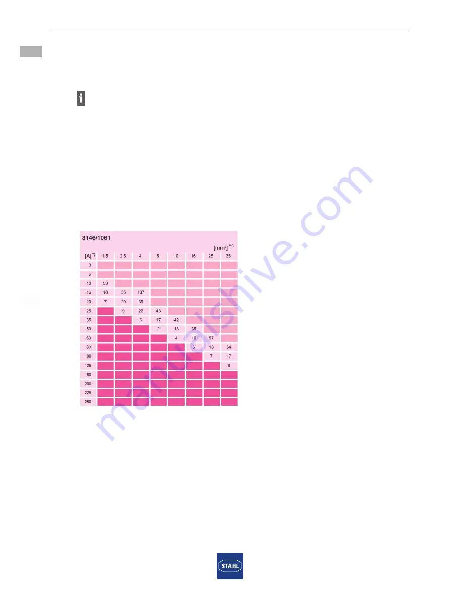
Taking enclosure 8146/1061 as an example: The maximum permitted number of conductors
can be ascertained using the following table.
06219E00
*) Current, **) conductor cross-section
Explanations of the table:
Each inserted conductor and each internal connection conductor must be counted.
Jumpers and protective conductors are not considered conductors.
Non-critical area (light area of the table)
The light area is non-critical in terms of heating up the enclosure. Circuits classified as being
in this area can be incorporated in the enclosure in any number.
Heat develops in every terminal box due to contact resistance at the terminals and the
cables installed in the enclosure. In order to ensure that the maximum permissible
temperatures of a terminal box are not exceeded, care should be taken that the current
load of the circuits installed in the terminal box does not exceed certain values!


