background image

303049 / 825060300230

2022-05-30·BA00·III·en·00

Appendix A

29

DE
EN

FR

IT

ES

RU

NL

DK

SE

FI

PT

GR

PL

CZ
SK

HU

SL

RO

BG

LV

LT

EE

CH

KR

CN

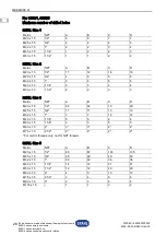
Ex d enclosure made of aluminium/flameproof enclosure

8250/0 series empty enclosure, 

8250/1 series terminal box, 

8250/5 series control panel/control station

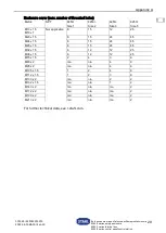
Enclosure cover (max. number of threaded holes)

For further technical data, see r

-

stahl.com.

Metric

NPT

8250/.

Size 1

8250/.

Size 2

8250/.

Size 3

8250/.

Size 5

M10 x 1.5

M10 x 1

Not applicable 8

15

12

25

M20 x 1.5

8

15

24

45

M24 x 1.5

8

15

24

45

M25 x 1.5

8

15

24

45

M32 x 1.5

6

12

12

25

M36 x 1.5

6

12

12

25

M75 x 1.5

2

4

3

6

M80 x 2

n/a

n/a

4

9

M95 x 2

n/a

n/a

4

6

M105 x 1.5

1

2

4

6

M112 x 1.5

1

2

3

6

M130 x 2

n/a

n/a

2

2

M132 x 1.5

n/a

n/a

1

2

M140 x 2

n/a

n/a

n/a

2

M172 x 2

n/a

n/a

n/a

2

M190 x 2

n/a

n/a

n/a

2

M210 x 2

n/a

n/a

n/a

2

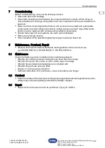
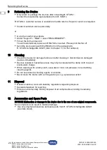
Summary of Contents for 294281

Page 1: ...eihe 8250 0 Leergeh use Reihe 8250 1 Klemmenkasten Reihe 8250 5 Steuerung Steuerkasten Betriebsanleitung Additional languages r stahl com DE EN FR IT ES RU NL DK SE FI PT GR PL CZ SK HU SL RO BG LV LT...

Page 2: ...erheit 5 3 1 Bestimmungsgem e Verwendung 5 3 2 Qualifikation des Personals 5 3 3 Restrisiken 6 4 Transport und Lagerung 7 5 Produktauswahl Projektierung und Modifikation 8 5 1 Zus tzliche Bohrungen im...

Page 3: ...nzung aktualisieren Die Originalbetriebsanleitung ist die deutsche Ausgabe Diese ist rechtsverbindlich in allen juristischen Angelegenheiten 1 3 Weitere Dokumente Datenblatt EU Baumusterpr fbescheini...

Page 4: ...ma nahmen zum Tod oder zu schweren Verletzungen mit bleibenden Sch den f hren kann WARNUNG Gefahrensituation die bei Nichtbeachtung der Sicherheitsma nahmen zu schweren Verletzungen f hren kann VORSIC...

Page 5: ...eichen der Zonen 1 und 2 sowie 21 und 22 Die Leergeh use 8250 0 Klemmenk sten 8250 1 und Steuerung 8250 5 werden in verschiedenen Gr en hergestellt Zur bestimmungsgem en Verwendung geh rt die Beachtun...

Page 6: ...t auf Besch digung pr fen Besch digungen umgehend an R STAHL melden Ger t in Originalverpackung trocken keine Betauung in stabiler Lage und sicher vor Ersch tterungen lagern Geh use Ex Spaltfl che Ei...

Page 7: ...chutz aufgehoben werden Explosionen mit t dlichen oder schweren Verletzungen von Personen k nnen die Folge sein Montage Installation Inbetriebnahme und Instandhaltung nur durch qualifizierte und autor...

Page 8: ...w sserungs oder Klimastutzen best cken die f r den Einsatz in explosionsgef hrdeten Bereichen nachweislich zugelassen sind und dem IP Schutz entsprechen Beispiele IECEx Certificate of Conformity Unben...

Page 9: ...hl und Einsatztemperatur der Komponenten und Dichtungen Angaben auf dem Typschild des Ger ts ber cksichtigen Nutzbare Fl che Kollisionsrahmen f r Anbaukomponenten ermitteln siehe Kapitel Anhang B Ma z...

Page 10: ...r Bereich beschrifteter Tabellenteil Dieser Tabellenteil zeigt die maximal zul ssige Leiterzahl unter Ber cksichtigung der Leiterquerschnitte und der die Leiter belastenden Dauerstr me Beim Anwenden d...

Page 11: ...57 8 75 8 10 92 8 10 115 6 8 143 6 8 170 6 6 200 4 6 230 4 6 260 4 6 315 4 4 360 4 400 500 30 30 29 18 15 12 9 9 0 0 0 0 0 0 0 0 max Anzahl der Klemmen je nach oben genannter Geh usegr e und Querschn...

Page 12: ...5 12 16 143 10 14 170 20 12 200 8 10 230 8 10 260 8 10 315 6 8 360 6 400 500 76 76 76 48 40 34 12 12 10 8 8 0 0 0 0 0 max Anzahl der Klemmen je nach oben genannter Geh usegr e und Querschnitt bzw max...

Page 13: ...43 14 18 170 12 16 200 10 12 230 10 14 260 10 12 315 8 12 360 8 400 500 156 156 156 99 78 66 32 32 26 16 16 0 0 0 0 0 max Anzahl der Klemmen je nach oben genannter Geh usegr e und Querschnitt bzw max...

Page 14: ...26 170 18 22 200 16 20 230 14 20 260 16 20 315 14 16 360 12 400 500 558 558 558 390 312 246 64 64 10 10 10 10 10 5 8 5 max Anzahl der Klemmen je nach oben genannter Geh usegr e und Querschnitt bzw max...

Page 15: ...rheit ver ndern Zus tzliche Klemmstellen Klemmentyp Anzahl Querschnitt und Strombelastung ermitteln siehe Kapitel Technische Daten Pr fen ob sich durch die Nachbest ckung die Typschilddaten ndern Quer...

Page 16: ...Montage Deckel oben H ngende Montage berh ngender Deckel nicht zul ssig Freiraum f r Deckel ffnung ber cksichtigen 16523E00 GEFAHR Explosionsgefahr durch unzureichende Verschraubung des Geh uses Nich...

Page 17: ...bbildung Anzugsdrehmoment siehe Kapitel Technische Daten 16155E00 6 1 2 Umgebungsbedingte Einbaubedingungen Bei freier Bewitterung kann das explosionsgesch tzte Ger t mit Schutzdach oder wand ausger s...

Page 18: ...els mit einem s urefreiem Fett das nach EN 60079 14 geeignet ist z B Hevolit behandeln 19315E00 Bei Geh usegr e 5 Zus tzlichen Positionsstift auf der Seite die den Scharnieren gegen berliegt in das da...

Page 19: ...effen Weitere Informationen und Anweisungen hierzu erhalten Sie gerne auf Anfrage von Ihrem zust ndigen Vertriebskontakt GEFAHR Explosionsgefahr durch starke Erw rmung im Geh useinneren Nichtbeachten...

Page 20: ...itel Technische Daten Alle blanken nicht spannungsf hrenden Metallteile in das Schutzleitersystem einbeziehen u erer Schutzleiteranschluss 16137E00 Schutzleiter au en entweder an Geh useseite A oder D...

Page 21: ...itel Technische Daten ber cksichtigen verst rkt sind um Verformungen zu vermeiden Eigensichere Stromkreise In eigensicheren Stromkreisen nur isolierte Kabel und Leitungen mit einer Pr fspannung von mi...

Page 22: ...l Technische Daten GEFAHR Explosionsgefahr durch besch digte Spaltfl chen Nichtbeachten f hrt zu t dlichen oder schweren Verletzungen Geh usedeckel stets vorsichtig anheben abnehmen und aufsetzen Sich...

Page 23: ...fizierte Komponenten ersetzen Sicherstellen dass Dichtungen und Dichtungssysteme sauber und unbesch digt sind Gegebenenfalls Fremdk rper entfernen Pr fen ob alle vorgeschriebenen Anzugsdrehmomente ein...

Page 24: ...R STAHL Schaltger te GmbH senden Adresse siehe Kapitel 1 1 10 Reinigung Ger t vor und nach der Reinigung auf Besch digung pr fen Besch digte Ger te sofort au er Betrieb nehmen Zur Vermeidung elektrost...

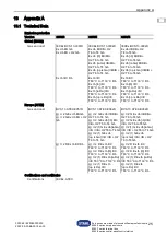
Page 25: ...is Da IIIC T80 C T130 C Db Ex tb IIIC T80 C T130 C Db Ex tb ib IIIC T80 C T130 C Db Ex tb ia Da IIIC T80 C T130 C Db Ex tb op is Da IIIC T80 C T130 C Db Europa ATEX Gas und Staub BVS 13 ATEX E057U BVS...

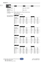
Page 26: ...ne Lackierung Umgebungs temperatur T6 T5 T4 T6 T5 T4 W W W W W W 40 C 89 133 244 75 113 211 50 C 63 104 211 52 87 181 60 C 38 76 179 31 63 153 70 C 16 50 148 13 41 126 8250 Gr e 2 Standard Lackierung...

Page 27: ...nd die Angaben der jeweiligen Hersteller zu ber cksichtigen Betriebstemperatur max 200 C Relative Feuchte keine Betauung 95 8250 0 Verwendung in H he 2000 m andere auf Anfrage Mechanische Daten Geh us...

Page 28: ...B C D M20x1 5 1 2 5 5 7 7 M25x1 5 3 4 2 2 4 5 M32x1 5 1 2 2 3 4 M40x1 5 1 1 4 1 2 2 3 M50x1 5 1 1 2 1 1 2 2 metrisch NPT A B C D M20x1 5 1 2 11 12 16 16 M25x1 5 3 4 4 6 5 8 M32x1 5 1 3 4 5 5 M40x1 5 1...

Page 29: ...eckel max Anzahl Gewindebohrungen Weitere technische Daten siehe r stahl com Metrisch NPT 8250 Gr e 1 8250 Gr e 2 8250 Gr e 3 8250 Gr e 5 M10x1 5 M10x1 entf llt 8 15 12 25 M20x1 5 8 15 24 45 M24x1 5 8...

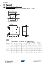
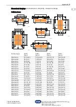
Page 30: ...Abmessung u ere Abmessung Einbauma auf Geh use mit Streifen mit Scharnier Abmessung A B C D E F G H I J K L Gr e 1 250 9 84 150 5 91 92 3 62 325 12 79 225 8 86 119 4 69 210 8 27 150 5 91 210 8 27 250...

Page 31: ...100 3 94 202 7 95 Ma D 15 5 0 61 18 0 71 25 5 1 00 30 1 18 Ma E 27 1 06 30 1 18 30 1 18 46 1 81 Ma F 41 1 61 50 1 97 81 5 3 21 182 7 17 Ma G 48 1 89 58 2 28 90 3 54 202 7 95 Ma H 176 6 93 206 8 11 27...

Page 32: ...8250 0 series empty enclosure 8250 1 series terminal box 8250 5 series control panel control station Operating instructions Additional languages r stahl com DE EN FR IT ES RU NL DK SE FI PT GR PL CZ...

Page 33: ...ice 4 3 Safety 5 3 1 Intended Use 5 3 2 Personnel Qualification 5 3 3 Residual Risks 6 4 Transport and Storage 7 5 Product Selection Project Engineering and Modification 8 5 1 Additional Drilled Holes...

Page 34: ...nstructions every time R STAHL issues an amendment The original instructions are the German edition They are legally binding in all legal affairs 1 3 Further Documents Data sheet EU Type Examination C...

Page 35: ...an result in fatal or severe injuries causing permanent damage if the safety measures are not complied with WARNING Dangerous situation which can result in severe injuries if the safety measures are n...

Page 36: ...r use in Zone 1 2 21 and 22 hazardous areas 8250 0 series empty enclosures 8250 1 series terminal boxes and 8250 5 series control panels come in a range of different sizes Intended use includes comply...

Page 37: ...eport any damage to R STAHL immediately Store the device in its original packaging in a dry place with no condensation and make sure that it is stable and protected against the effects of vibrations a...

Page 38: ...persons Otherwise the explosion protection may be rendered ineffective This may result in explosions causing serious or even fatal injury Only have mounting installation commissioning and maintenance...

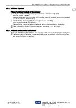
Page 39: ...the enclosure only with suitable equipment e g cable entries stopping plugs drain valves or breathers that is verifiably approved for use in hazardous areas and meets the requirements of the IP protec...

Page 40: ...e device s rating plate to help you determine which components and seals to use and what operating temperatures they will need to be able to withstand Calculate the usable area collision frame for add...

Page 41: ...e enclosure in any number Critical area labelled area of the table This part of the table shows the maximum permissible number of conductors considering the conductor cross sections and the continuous...

Page 42: ...92 8 10 115 6 8 143 6 8 170 6 6 200 4 6 230 4 6 260 4 6 315 4 4 360 4 400 500 30 30 29 18 15 12 9 9 0 0 0 0 0 0 0 0 Maximum number of terminals depending on the aforementioned enclosure size and cros...

Page 43: ...14 170 20 12 200 8 10 230 8 10 260 8 10 315 6 8 360 6 400 500 76 76 76 48 40 34 12 12 10 8 8 0 0 0 0 0 Maximum number of terminals depending on the aforementioned enclosure size and cross section or...

Page 44: ...2 16 200 10 12 230 10 14 260 10 12 315 8 12 360 8 400 500 156 156 156 99 78 66 32 32 26 16 16 0 0 0 0 0 Maximum number of terminals depending on the aforementioned enclosure size and cross section or...

Page 45: ...00 16 20 230 14 20 260 16 20 315 14 16 360 12 400 500 558 558 558 390 312 246 64 64 10 10 10 10 10 5 8 5 Maximum number of terminals depending on the aforementioned enclosure size and cross section or...

Page 46: ...h the safety notes see the Safety chapter Ascertain additional clamping units terminal type quantity cross section and current load see the Technical data chapter Check whether the rating plate data c...

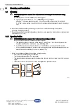
Page 47: ...ed above the ground and the cover must not be at an angle Take into account the clearance that is required to open the cover 16523E00 DANGER Explosion hazard due to insufficient fastening of the enclo...

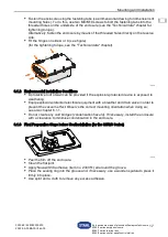
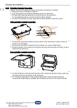
Page 48: ...the tightening torque see the Technical data chapter 16155E00 6 1 2 Environmental Installation Conditions A protective roof or wall can be provided if the explosion protected device is exposed to wea...

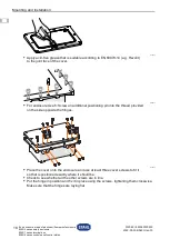
Page 49: ...se that is suitable according to EN 60079 14 e g Hevolit to the joint face of the cover 19315E00 For enclosure size 5 Screw an additional positioning pin into the thread provided on the side opposite...

Page 50: ...n the operating location Further information and instructions on this can be obtained on request from your designated sales contact DANGER Explosion hazard due to intense heating inside the enclosure...

Page 51: ...the Technical data chapter Connect all uncoated non live metal parts to the protective conductor system Outer protective conductor connection 16137E00 Connect the protective conductor to the outside...

Page 52: ...rd IEC EN 60079 7 and the information on the voltage that occurs see the Technical data chapter are reinforced to prevent deformation Intrinsically safe circuits In intrinsically safe circuits use onl...

Page 53: ...ten them to the specified tightening torques see the Technical data chapter DANGER Explosion hazard due to damaged joint faces Non compliance results in fatal or severe injuries Always carefully lift...

Page 54: ...ertified components Ensure that seals and seal systems are clean and undamaged Remove any foreign objects Check whether all the specified tightening torques have been observed 8 Maintenance Overhaul R...

Page 55: ...MA form in the packaging to R STAHL Schaltger te GmbH refer to chapter 1 1 for the address 10 Cleaning Check the device for damage before and after cleaning it Decommission damaged devices immediately...

Page 56: ...Da IIIC T80 C to T130 C Db Ex tb IIIC T80 C to T130 C Db Ex tb ib IIIC T80 C to T130 C Db Ex tb ia Da IIIC T80 C to T130 C Db Ex tb op is Da IIIC T80 C to T130 C Db Europe ATEX Gas and dust BVS 13 ATE...

Page 57: ...class 8250 Size 1 Standard paint Unpainted Ambient temperature T6 T5 T4 T6 T5 T4 W W W W W W 40 C 89 133 244 75 113 211 50 C 63 104 211 52 87 181 60 C 38 76 179 31 63 153 70 C 16 50 148 13 41 126 8250...

Page 58: ...he specifications of the respective manufacturer must be taken into account here Service temperature max 200 C Relative humidity no condensation 95 8250 0 Use at height 2000 m others on request Mechan...

Page 59: ...1 2 5 5 7 7 M25 x 1 5 3 4 2 2 4 5 M32 x 1 5 1 2 2 3 4 M40 x 1 5 1 1 4 1 2 2 3 M50 x 1 5 1 1 2 1 1 2 2 Metric NPT A B C D M20 x 1 5 1 2 11 12 16 16 M25 x 1 5 3 4 4 6 5 8 M32 x 1 5 1 3 4 5 5 M40 x 1 5...

Page 60: ...number of threaded holes For further technical data see r stahl com Metric NPT 8250 Size 1 8250 Size 2 8250 Size 3 8250 Size 5 M10 x 1 5 M10 x 1 Not applicable 8 15 12 25 M20 x 1 5 8 15 24 45 M24 x 1...

Page 61: ...Internal dimensions External dimensions Installation dimensions On enclosure With strip With hinge Dimensions A B C D E F G H I J K L Size 1 250 9 84 150 5 91 92 3 62 325 12 79 225 8 86 119 4 69 210 8...

Page 62: ...61 18 0 71 25 5 1 00 30 1 18 Dimension E 27 1 06 30 1 18 30 1 18 46 1 81 Dimension F 41 1 61 50 1 97 81 5 3 21 182 7 17 Dimension G 48 1 89 58 2 28 90 3 54 202 7 95 Dimension H 176 6 93 206 8 11 275...

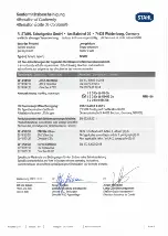
Page 63: ...Db BVS 13 ATEX E 057 U DEKRA Testing and Certification GmbH Dinnendahlstra e 9 44809 Bochum Germany NB0158 NB0158 Produktnormen nach Niederspannungsrichtlinie Product Standards according to Low Voltag...

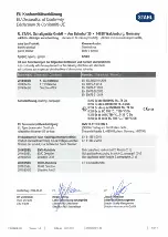
Page 64: ...H2 T6 T4 Gb II2 G Ex db op is IIB IIB H2 T6 T4 Gb II2 D Ex tb NIC T80 C T130 C Db II2 D Ex tb ia IIIC T80 C T130 C Db II 2 D Ex tb op is IIIC T80 C T130 C Db C 0158 EU Baumusterpr fbescheinigung EU T...

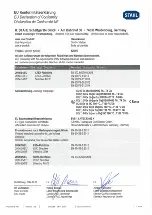
Page 65: ...des produit pour la Directive Basse Tension 2014 30 EU 2014 30 EU 2014 30 UE 2011 65 EU 2011 65 EU 2011 65 UE EMV Richtlinie EMC Directive Directive CEM RoHS Richtlinie RoHS Directive Directive RoHS...

Reviews: