

1. Description
The Stahl Tools DSDS Soldering & Desoldering Station is a high-performance and multi-function station developed by Stahl
Tools to use in electronic product research, production, and rework. This tool is used in the fields of electronic research,
teaching and production, especially for repairing and reworking electronic appliances and communication equipment.
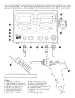
1.1 Control Unit
The soldering iron and the desoldering gun are controlled automatically by two micro-processors. The digital control
electronics, high-quality sensor and heat exchange system guarantee precise temperature control at the soldering tip. The
highest degree of temperature precision and optimal dynamic thermal behavior under load conditions is obtained by the
quick and accurate recording of the measured values in a closed control circuit. This design works especially well with lead-
free production techniques.
1.2 Soldering Iron
Soldering iron is 60W and offers a wide spectrum of optional soldering tips that can be used anywhere in the electronics field.
The high power and slim design makes this iron suitable for fine soldering work. The heating element is made of PTC and
the sensor on the soldering tip controls the soldering temperature quickly and accurately.
1.3 Desoldering Gun
Desoldering gun with a power of 80W has three optional tip sizes that can be used anywhere in the electronics field.
The high power and gun type design makes this iron suitable for fine desoldering work. The heating element is made of PTC
and the sensor on the desoldering tip controls the desoldering temperature quickly and accurately.
2. Technical Specification
Rated voltage range 110-130V AC 60Hz; rated power input 160W.
3. Operating Instruction
Place the soldering and desoldering guns in their holders separately. Then connect the plug to the receptacle on the station
and turn clockwise to tighten the plug nut. Check that the power switch is on the “OFF” position. Connect the control unit
to the power supply and switch on the power. Then a self-test is carried out in which all display elements are switched on
briefly. The electronic system then switches on automatically to the set temperature and displays this value.
Adjust the temperature and wait for the gun’s current read-out to reach the desired heat setting. Apply the tip of the soldering
gun to the solder joint and squeeze the trigger as soon as the solder melts.
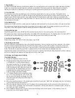
3.1 Display and Temperature Setting
The digital display:
1.
Shows the actual temperature of the tip.
2.
Shows the setting temperature. Press the UP
or DOWN button to set the digital display to
the desired heat setting. The set-point can be
changed for ±1
°
C by tapping the UP or DOWN
button. Holding the button down will change the
set-point quickly. The digital display will return
automatically to the actual value and the iron
heats up quickly to the desired setting.
3.
°
C/
°
F display: Switching the temperature display
from
°
C to
°
F by pressing the “
°
C/
°
F” button and
then the electronic system will display the actual
temperature
(1)
and setting temperature
(2)
in
°
F,
and vice versa.
4.
When the actual temperature on the soldering tip is less than the set-point, “HEAT ON” will display when the tip is heating
up to maintain the desired temperature.
5.
When the absolute offset is more than ±10
°
C between the actual temperature and the set-point on the soldering tip or
the nozzle, “WAIT” will display. This means that the temperature control system detects a non-stable situation. Pause for
a moment until “WAIT” disappears.
6.
When “ERROR” displays, there may be an issue with the temperature control system, or the soldering iron is not
connected to the control system correctly.
4


