background image

LAX 50 G

8

en

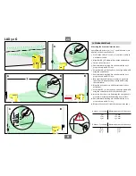
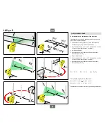
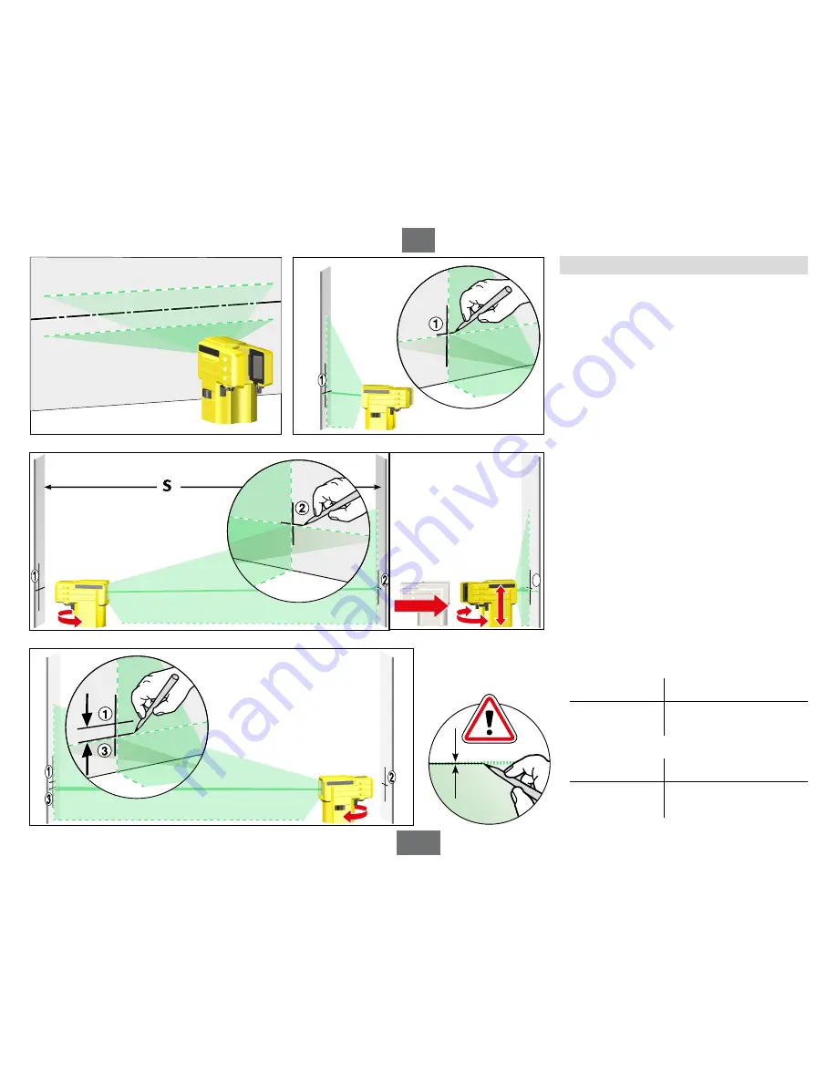
7.2 Horizontal check

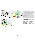
A Checking the horizontal laser line level


2 parallel walls at least 5m / 16’5”  apart (distance S) are 

required for the horizontal check.
1.  Position the LAX 50 G as close as possible to wall A on 

a horizontal surface.

2.  Align the LAX 50 G with wall A using the exit window.
3.  Switch on the laser unit. 
4.  Once automatic levelling has ended, mark the cross 

projected onto wall A. Point 1.

5.  Rotate the LAX 50 G through 180° and align with wall B 

using the exit window. 

6.  Once automatic levelling has ended, mark the cross 

projected onto wall B. Point 2.

7.  Now reposition the laser unit so that it is directly in 

front of wall B. Align the LAX 50 G with wall B using  

the exit window. 

8.  Move the laser line cross until it precisely coincides 

with point 2.  

9.  Rotate the LAX 50 G through 180° and align with wall A 

using the exit window. Do not adjust the height.

10. Move the laser line cross by turning the casing until it 

precisely coincides with the marking line of point 1.  

11. Once automatic levelling has ended, mark the cross 

projected onto wall A. Point 3.

12. Measure the vertical distance between points 1 and 3.

Distance S to the wall Maximum permissible distance:

5 m

  5.0 mm

10 m

10.0 mm

15 m

15.0 mm

Distance S to the wall Maximum permissible distance:

16’5”

   3/16”

   32’10”

3/8”

49’3”

5/8”

2

A

B

A

B

B

A

Summary of Contents for LAX 50 G

Page 1: ...Operating instructions How true pro s measure LAX 50 G ...

Page 2: ...ning 3 4 Components of the unit 4 5 Commissioning 5 5 1 Inserting batteries Battery replacement 5 5 2 Switching the unit on 5 6 Applications 6 7 Checking accuracy 7 7 1 Vertical check 7 7 2 Horizontal check 8 8 Care and maintenance 10 9 Recycling programme for our EU customers 10 10 Technical data 10 ...

Page 3: ...ays check that the unit is functioning correctly and accurately before you start work particularly if it has been exposed to heavy vibrations Do not use in explosive or corrosive environments Do not dispose of the batteries or unit with domestic waste Keep this user manual in a safe place and hand it over when passing the unit to another person 3 Before first commissioning Carefully read the safet...

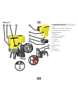
Page 4: ...ON OFF sliding switch with transport lock 4 Rough adjustment vial 5 Clamping jaws 6 Locking lever for clamping jaws 7 Battery compartment lid 8 Foot adapter 9 1 4 tripod socket 10 Foot 11 1 4 threaded screw 12 Magnets 13 Hanging hole 14 5 8 tripod socket 4 Components of the unit ...

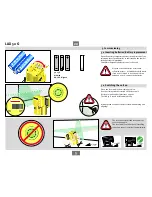
Page 5: ...riod remove the batteries 3 x 1 5 V Alkaline AA LR6 Mignon 5 1 Inserting batteries Battery replacement 5 Commissioning The laser lines flash if the laser unit is at too steep an angle The laser unit is outside the self levelling range and cannot level itself automatically Place the laser unit in the working position Use the sliding switch to switch on the laser unit Horizontal and vertical laser l...

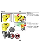
Page 6: ... the foot to fix the LAX 50 G in a specific position Thanks to the hanging hole and magnets it is even possible to attach the foot to construction elements The 5 8 tripod socket allows you to mount the unit on a construction tripod Use the 1 4 thread to secure the adapter on the foot then insert the LAX 50 G in the adapter Rotate the unit to ensure the laser lines are precisely aligned The 1 4 tri...

Page 7: ... you start work par ticularly if the unit has been exposed to heavy vibrations Horizontal check Vertical check 7 Checking accuracy 7 1 Vertical check Checking the vertical laser line Create a reference line e g with a plumb line Set up and align the LAX 50 G at distance Y in front of this reference line Compare the laser line with the reference line Do not allow the laser line to deviate from the ...

Page 8: ...to wall B Point 2 7 Now reposition the laser unit so that it is directly in front of wall B Align the LAX 50 G with wall B using the exit window 8 Move the laser line cross until it precisely coincides with point 2 9 Rotate the LAX 50 G through 180 and align with wall A using the exit window Do not adjust the height 10 Move the laser line cross by turning the casing until it precisely coincides wi...

Page 9: ...m the line exactly in front of the middle point position X 3 Switch on the unit 4 Measure the height of the laser line at the points Measurements X1 X3 5 Reposition the unit 6 Position the laser S 5m 16 5 from the line exactly in front of the middle point position Y 7 Measure the height of the laser line at the points Measurements Y1 Y3 1 X1 Y1 2 X2 Y2 3 X3 Y3 The following applies to the differen...

Page 10: ...g unit is a precision optical instrument and should be handled with care Window apertures display windows Dirty window glass impairs the optical function Clean the unit using only a soft cloth and a little water or if necessary a mild detergent Casing Clean the unit with a damp cloth Do not use solvents or thinners Do not immerse the unit in water Do not unscrew the laser unit Transport and storag...

Page 11: ...v Ullrich GmbH P O Box 13 40 D 76851 Annweiler Landauer Str 45 D 76855 Annweiler USA Canada STABILA Inc 332 Industrial Drive South Elgin IL 60177 www stabila com 49 63 46 309 0 49 63 46 309 480 info stabila de www stabila com ...

Reviews: