11
Pump Reassembly/Installing New Seal
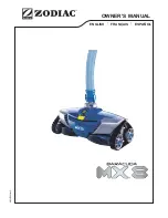
1. Ceramic seat must be clean and free of dirt, grease,
dust, etc. Wet outer edge with small amount of
liquid detergent; press ceramic seat into seal plate
cavity firmly and squarely with finger pressure
(Figure 11).
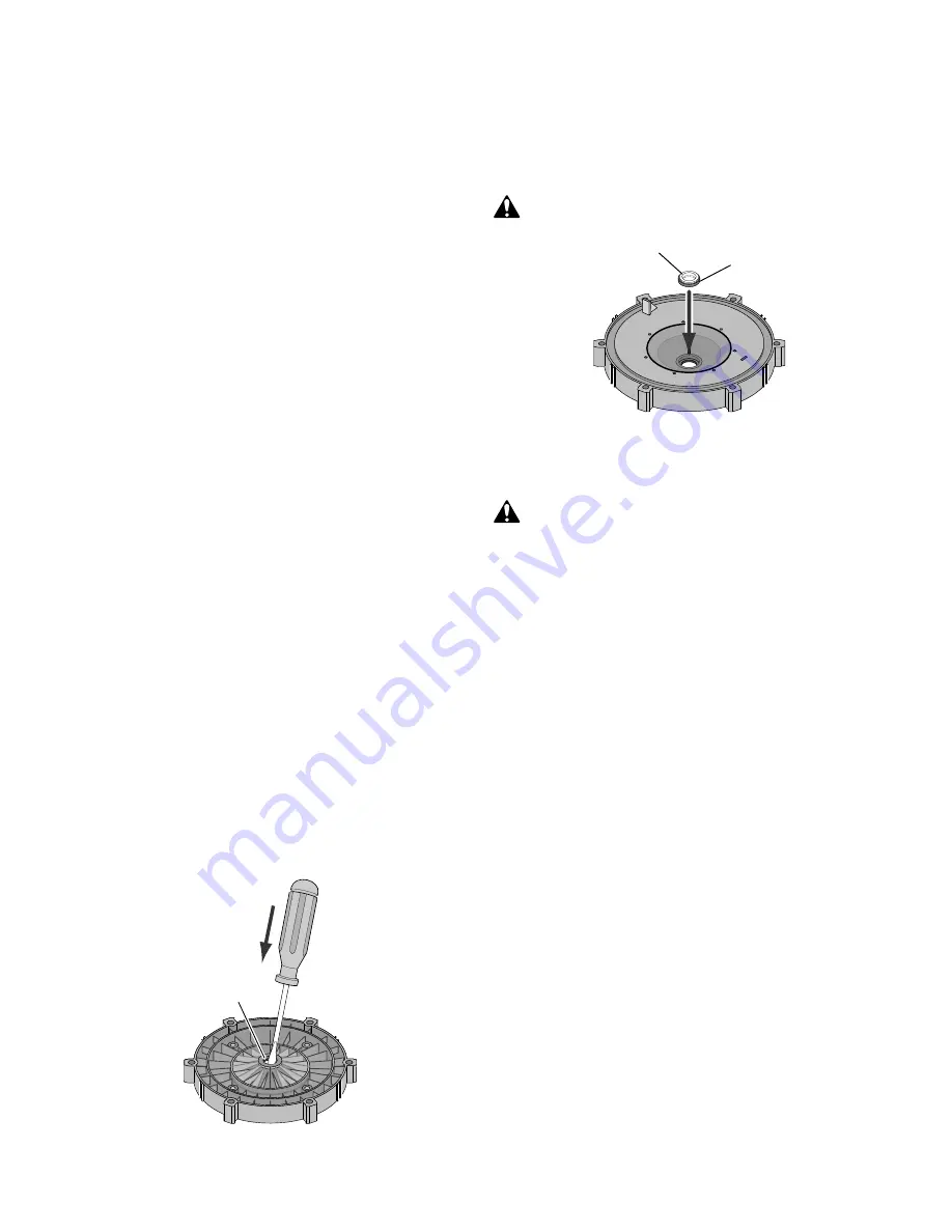
2. If ceramic seat will not locate properly, remove it,
place face up on bench and reclean cavity. Ceramic
seat should now locate.
3. If seat still will not locate properly, place a
cardboard washer over the polished face and use a
piece of 3/4" (19mm) standard pipe for pressing
purposes.
NOTICE: Be sure not to scratch or mar polished
surface or seal will leak.
4. Replace slinger on end of motor shaft so that
impeller sleeve will push it into position. If slinger
shows signs of wear or damage, replace it.
5. Remount seal plate on motor. Tighten bolts to 60-80
inch-lbs. (69-92 kg/cm) torque.
6. Apply a small amount of liquid detergent to inside
diameter of rotating half of seal.
7. Slide rotating seal member, polished carbon face
out, over impeller sleeve until rubber drive ring hits
back of impeller.
NOTICE: Be sure not to nick or scratch polished
seal face; seal will leak if face is damaged.
8. Screw impeller onto shaft (clockwise); this will
automatically locate seal in seal plate.
NOTICE: On 2 and 2-1/2 HP models; install
impeller gasket and lock screw (left-hand thread -
turn counterclockwise). Torque lock screw to 50-55
inch-lbs. (57.6-63 kg/cm).
9. Mount diffuser on seal plate; tighten screws to 10-
14 inch-lbs. (11.2-16.1 kg/cm) torque.
10. Assemble motor and seal plate to pump body with
nuts, flat washers and lock washers. Torque nuts to
120-130 in-lbs. (138-150 kg/cm).
11. Prime pump according to instructions on Page 9.
TROUBLESHOOTING
GUIDE
Read and understand safety and operating
instructions in this manual before doing any work on
pump!
Only qualified personnel should electrically test
pump motor!
FAILURE TO PUMP; REDUCED CAPACITY OR
DISCHARGE PRESSURE
Suction leaks/lost prime:
1. Pump must be primed; make sure that pump volute
and trap are full of water. See priming instructions,
Page 9.
2. Make sure there are no leaks in suction piping.
3. Make sure suction pipe inlet is well below the water
level to prevent pump from sucking air.
4. If suction trap gasket is defective, replace it.
5. Make sure pump is not trying to lift water more than
10'(3m).
6. Make sure suction pipe is at least 2" (51mm) in
diameter.
Clogged pipe/trap/impeller, worn impeller:
7. Make sure suction trap is not clogged; if it is, clean
trap and strainer.
8. Make sure impeller is not clogged (follow steps 1
through 7 under “Removing Old Seal”, Page 11;
check impeller for clogging; follow steps 7 through
11 under “Installing New Seal”, Page 11, for
reassembly).
9. Impeller and diffuser may be worn. If so, order
replacement parts from Repair Parts List, Pages 12
and 13.
Figure 10
Mechanical seal
ceramic seat
Polished
surface
Rubber
surface
Figure 11
Summary of Contents for MPEA6D-146L
Page 15: ...15...
Page 16: ...S243 Rev A 04 15 10 S243...