


UM0214
Software
7/9
Figure 6.
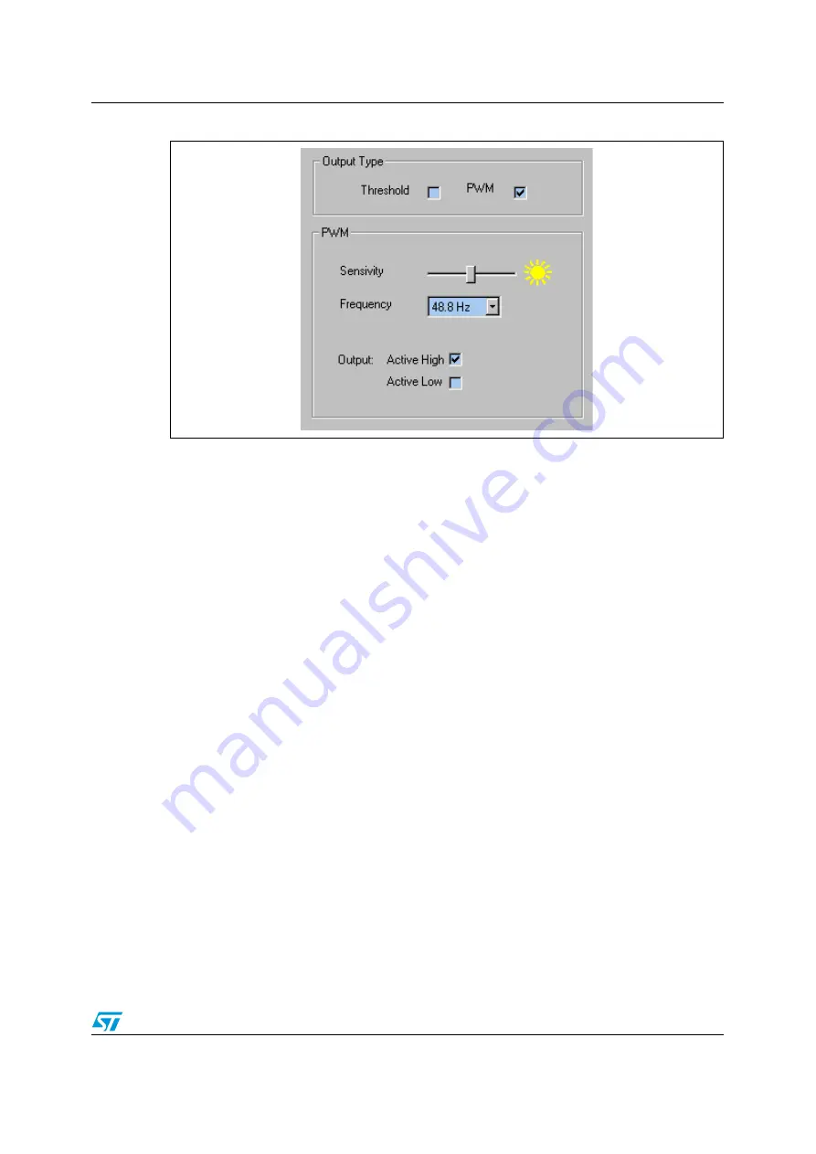
PWM option
Threshold
The
Threshold
options include upper and lower threshold setting with
Greater Than / Less
Than
tick boxes for these thresholds and
Active High / Low
O
utput
.
The default is for the
Upper Threshold
to be set to 19.531 W/m2 with the
Less Than
box
ticked (as shown in
), the output is set to
Active High
. In this mode the LED on the
demo board should be on in normal "office" lighting conditions.
When the user hits the
START
button the LED output will be mimicked by the
Threshold
Indication
box which will turn yellow when the LED is on. If the threshold is crossed the LED
on the demo board turns off. If the output is changed to
Active Low
the LED (and threshold
indication box) the output is inverted (i.e. the LED will turn on if the threshold is crossed).
The user can set the thresholds by hitting the
SET
button beside the relevant threshold. This
will set the threshold to the current light level experienced by the sensor when the button is
hit.
Note:
The Thresholds can only be set when the demo app is running.
The thresholds are activated using the tick boxes, that is the threshold is only activated
when the
< or >
for that threshold is ticked. The user can deactivate a threshold by
deselecting the ticks.
PWM
When the
Output Type
is changed to
PWM
the
Sensitivity
and
Frequency
options are
displayed as shown in
The
Sensitivity
and
Frequency
can be changed by using the slider and drop down menu.
Units
The units displayed in the Y Bar outputs can be changed by using the drop down menu
beside the
About
button. This will change the units that are displayed in the box under the
pixel's light bar and also change the displayed value of any thresholds that are set.


