background image

System overview

UM0874

14/33

Doc ID 16844 Rev 1

4 System 

overview

4.1 

Hardware design description

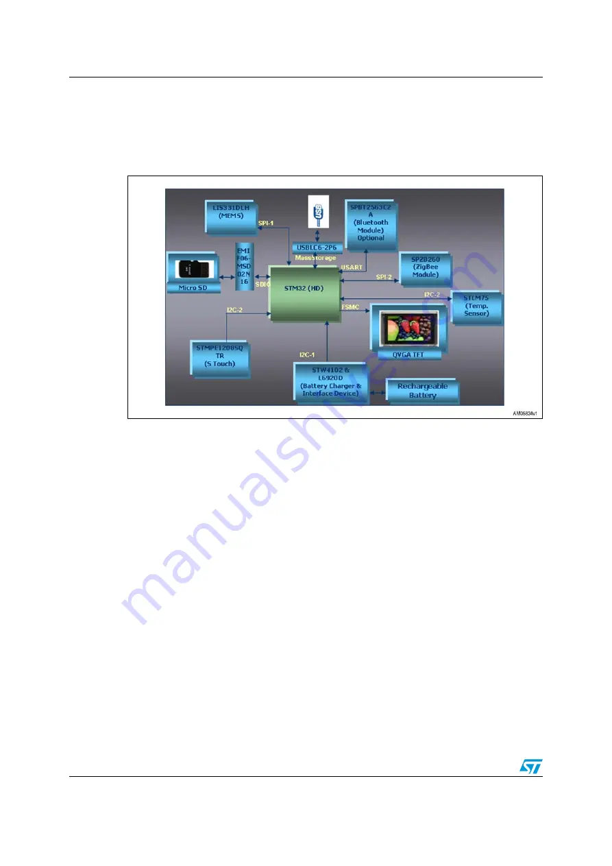
Figure 16.

System block diagram

The hardware block diagram is given in 

Figure 16

. As shown, the STM32 microcontroller is 

the main controller of the system.  

4.1.1 Microcontroller 

(STM32)

The STM32 is a 32-bit MCU based on the popular ARM 32-bit Cortex™-M3 CPU running at 
72 MHz with performance of 90 DMIPS with 1.25 DMIPS/MHz. The memories embedded in 
it contain up to 20 Kbytes of SRAM and 128 Kbytes of flash memory. The microcontroller 
has single-cycle multiplication and hardware division. It has 80 fast general-purpose IOs to 
enhance the overall performance. The IOs are 5 V tolerant.

The microcontroller has up to 9 communication interfaces which include two I

2

Cs 

(400 kHz), three USARTs (4.5 Mbps), two SPIs (18 MHz), CAN 2.0B active interface and 
USB 2.0 (12 Mbps) full-speed interface. For more details, please refer to the STM32F103VE 
datasheet. 

For the digital photo frame application, the firmware is using the two SPIs, two I

2

Cs, SDIO, 

FSMC and USB interfaces. One of the SPIs is interfaced with  MEMS and the other one with 
the ZigBee

®

 module. The SD card is interfaced with SDIO and the TFT with FSMC. The 

STLM75 and STMPE1208SQTR use I

2

C-2 and the STW4102 uses I

2

C-1 to communicate 

with the controller.

The microcontroller works on a single voltage from 2 V to 3.6 V, unlike several 
microcontrollers requiring dual voltage. In this application the voltage bus is managed with 
3.3 V.

www.BDTIC.com/ST

Summary of Contents for UM0874

Page 1: ...s are the perfect example of enjoying these digital images The functionality of displaying images with the STM32 shows the capability of this microcontroller in multimedia applications The STM32 has a...

Page 2: ...nnector 15 4 1 5 Micro SD connector 15 4 1 6 MEMS 15 4 1 7 Temperature sensor 15 4 1 8 S Touch based keypad 15 4 1 9 Bluetooth module 15 4 1 10 ZigBee module 15 4 1 11 Power supply unit 16 4 2 Firmwar...

Page 3: ...time screen on the TFT display 10 Figure 10 HomePageMenu jpg 10 Figure 11 STM32 based graphical panel display with touch keys notation 11 Figure 12 Demonstration board top side 12 Figure 13 Demonstrat...

Page 4: ...lay the date time and calendar MEMS used to rotate the image as per the TFT alignment Micro SD card interfaced through SDIO USB mini B connector Uses the mass storage for connectivity to PC User will...

Page 5: ...unit IDCT Inverse discrete cosine transform MMC SD Multimedia card secured drive MPEG Moving picture experts group FAT File allocation table TFT Thin film transistor LCD Liquid crystal display SPI Ser...

Page 6: ...etting up the board The STM32 based graphical display panel demonstration board can be set up as follows 1 Copy some JPEG images to the micro SD card 2 Connect the micro SD card to the demonstration b...

Page 7: ...voltage power supply can be connected 6 Three icons appear on the home page Digital Photo Frame USB Mass storage and Date Time Temperature Figure 3 Home page on the TFT display 7 Any of the above men...

Page 8: ...Doc ID 16844 Rev 1 Figure 5 Start of DPF demonstration on the TFT display 10 After selecting one of the speeds the image slideshow starts Figure 6 Start of DPF demonstration with medium speed on the T...

Page 9: ...ill appear according to the frame alignment 14 To set the time and date press the C calendar key The following window will pop up Select one of the options Set Time or Set Date Figure 8 Set date and t...

Page 10: ...ough Windows Explorer using a card reader or the demonstration board in mass storage mode 2 Copy any JPEG images to the micro SD card 3 Insert the card into the micro SD slot on the board 4 Program th...

Page 11: ...mponent layout to help the user to locate different components sections on the board V 3LIDE SWITCH ON OFF OME KEY ANCEL KEY EFT KEY 2IGHT KEY NTER KEY 5P KEY 3LOW KEY OWN KEY LACK KEY 0LAY PAUSE EDIU...

Page 12: ...1 Figure 12 Demonstration board top side Figure 13 Demonstration board bottom side V 4 4 34OUCH BASED KEYPAD V I ON BATTERY CONNECTOR Z CRYSTAL K Z CRYSTAL 34 34 0OWER ON OFF SWITCH 53 MINI CONNECTOR...

Page 13: ...UM0874 Getting started Doc ID 16844 Rev 1 13 33 Figure 14 Hardware layout top side Figure 15 Hardware layout bottom side www BDTIC com ST...

Page 14: ...performance The IOs are 5 V tolerant The microcontroller has up to 9 communication interfaces which include two I2 Cs 400 kHz three USARTs 4 5 Mbps two SPIs 18 MHz CAN 2 0B active interface and USB 2...

Page 15: ...d to program the microcontroller through JTAG and debug the firmware 4 1 5 Micro SD connector The micro SD connector is provided for the micro SD card It is interfaced with SDIO 4 1 6 MEMS MEMS LIS331...

Page 16: ...power supply unit contains components like the battery charger system STW4102 step up converter L6920 voltage regulator LD1117D33TR and ESD protection on the USB bus USBLC6 Power MOSFET STT5PF20V See...

Page 17: ...for this application One of the SPIs SPI1 is interfaced with MEMS and the other one SPI2 with the ZigBee module I2C1 is with battery charger and I2C2 with temperature sensor and S Touch SDIO is the i...

Page 18: ...ww st com 4 2 3 SD MMC library The SD MMC cards are very common in mass storage media and are frequently used in many digital cameras and cell phones SD cards are found in different forms According to...

Page 19: ...st extracts the RGB data from the JPEG luminance and chrominance components namely Y Cr and Cb using Huffman decoding and IDCT Inverse Discrete Cosine Transform Each pixel has now 3 bytes of data 1 by...

Page 20: ...B 17567 3 B06 B 3 B 7 B 706 3 B BQ66 3 B B6 3 B76B67B6 3 B06 B6 2B 3 B B56 3 B 76B67B6 3 B B0 62 Q567 3 B BQ 6 1 9 3 B3 0B 1 3 B 7B576 3 B 7B 76 3 B 7B7 3 B 7B5 3 B 7B 83 Q567 26 B 1 26 B287 3 B26 B 1...

Page 21: ...6 2B 3 B 7 B 7 3 B06 B6 2B Q567 3 B06 B6 2B 3 B B56 3 B BQ 5 3 B BQ5 3 B BQ567 3 B B 3 B B 3 B B 3 B B 3 B B 3 B B 3 B B 3 B B 3 B B 3 B B 3 B B 3 B B 3 B B 3 B B 3 B B 3 B B 1 1 1 9 3 B BQ 6 9 3 B B...

Page 22: ...6 3 B76B 17 3 B 7B576 3 B 7B 76 3 B 7B7 3 B 7B5 3 B 7B 83 9 26 B 1 3 B 7B 267 83 3 B 7B5 3 B 7B7 9 21 9 26 B 1 3 B 7B B287 3 B 7B B287 9 3 B 7B B 1 3 B 7B B 1 3 B 7B B287 7B 83 7B 83 7B 3 2B 3 B 7B5 6...

Page 23: ...Q X X Q Q X 9 X 9 8 6 8 6 9 B 2 1 1 6 1 6 6 2 6 17 5 6 59 17 1 1 9 1 5 6 59 5 5 5 PLOL 2 0 5 PLOL 2 0 S S 5 N 5 N 5 N 5 N 5 N 5 N 5 0 5 0 X 9 X 9 5 N 5 N 5 5 Q Q X X X X 5 N 5 N X X 8 86 3 8 86 3 1 2...

Page 24: ...9 9 9 3 B76B67B6 3 B76B67B6 3 B76B5 6 7 3 B76B5 6 7 728 6 7 21 5 N 5 N 8 6703 6475 8 6703 6475 3 2B 6B 1B 6B 1B 6B 1B 6B 1B 3 2B 6B 1B 3 2B 3 2B 3 2B B B 5 6 7B1 6B 1B 6B 1B 3 2B 3 2B 6 7 6 7B 17 B 17...

Page 25: ...charger system QFN24 STMicroelectronics STW4102IQT U4 3 3 V out voltage regulator SO 8 STMicroelectronics LD1117D33TR U5 Step up converter TSSOP8 STMicroelectronics L6920D U6 ESD protection for USB SO...

Page 26: ...2 pin through hole Jauch Q 0 032768 MMTF32 12 5 30 Y2 8 MHz 2 pin through hole Jauch Q 8 0 SS4 22 30 30 Connectors jumpers and switches SW1 Power switch slide switch SPDT right angle 3 pin 2 54 mm pit...

Page 27: ...Any J7 CON10 10 pin header 2 5 mm pitch through hole Any J9 J10 CON8A Header 2 x 4 pin 2 54 mm x 2 54 mm pitch through hole Any Connectors jumpers and switches J11 J12 CON8A Socket 2 x 4 pin 2 54 mm...

Page 28: ...C2 C3 C4 C5 C6 C11 C12 C14 C17 C22 C23 C29 C33 C34 C35 C36 C37 100 nF SMD0805 Any C7 22 F SMD0805 Any C8 C16 47 F 10 V EIA 3528 21 size A Any C9 C10 1 F EIA 3528 21 size A Any Table 3 BOM continued Ca...

Page 29: ...SMD0805 Any C38 6 pF SMD0805 Any C40 C41 C42 C43 C45 C46 C48 C49 C50 C51 Not mounted SMD0805 C44 C47 1 pF SMD0805 Inductors L1 L2 10 H SMD0805 Any Resistors R1 R2 R3 R4 R13 R15 R17 R18 R20 R28 R31 10...

Page 30: ...R24 DNM SMD0805 Any R27 30 m SMD0805 Any R29 R38 2 M SMD0805 Any R30 15 k SMD0805 Any R35 18 k DNM SMD0805 Any R37 16 k SMD0805 Any R39 200 k SMD0805 Any R40 22 k SMD0805 Any R44 1 k SMD0805 Any R45 R...

Page 31: ...T TFT 320 x 240 Module MB694 Ampire MB694 Micro SD card micro SD card Any BT1 Li coin battery 3 V CR2032 Any BT2 Li Ion rechargeable battery 3 3 V Any 1 Table 3 BOM continued Category Ref des Componen...

Page 32: ...Revision history UM0874 32 33 Doc ID 16844 Rev 1 6 Revision history Table 4 Document revision history Date Revision Changes 30 Jun 2010 1 Initial release www BDTIC com ST...

Page 33: ...OF MERCHANTABILITY FITNESS FOR A PARTICULAR PURPOSE AND THEIR EQUIVALENTS UNDER THE LAWS OF ANY JURISDICTION OR INFRINGEMENT OF ANY PATENT COPYRIGHT OR OTHER INTELLECTUAL PROPERTY RIGHT UNLESS EXPRES...

Reviews: